Week -2
1. Door Bell
The following blocks are used to model and simulate the door bell using a solenoid
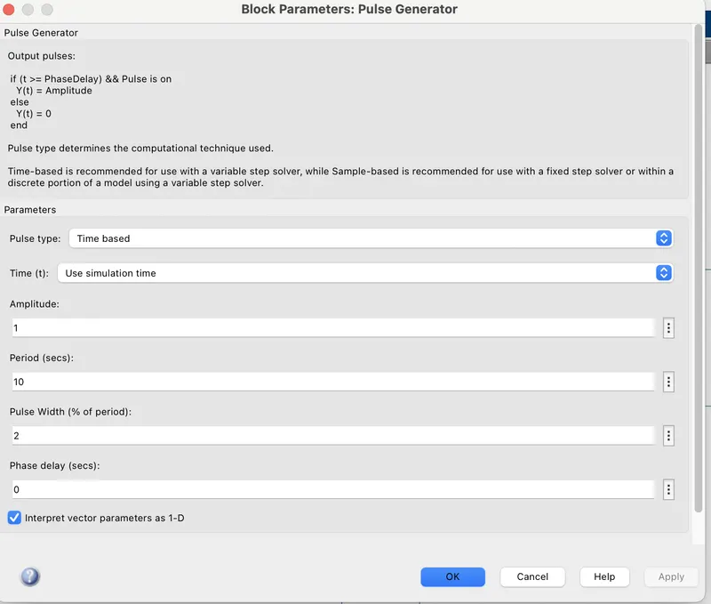
Pulse Generator
Time based pulse type signal is used as a signal for the physical switch with a time delay of 2 seconds.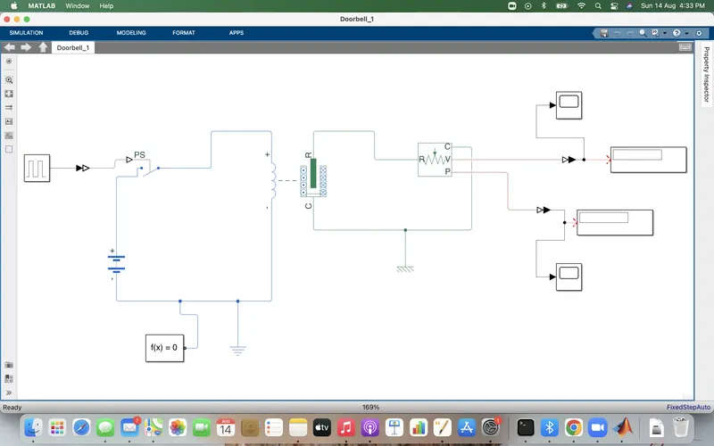
Simulink to PS converter: Converts simulink signals to the respective Physical signals
PS Switch: To switch is controlled by an external physical signal. If the external physical signal is greater than the threshold, then the switch is closed, else the switch is open
Battery: To provide a voltage source to the circuit
Solenoid: To convert the electrical energy in to mechanical energy with the movement of the plunger from port R to C due to electromagnetic field around the coil.
Battery, PS Switch and soleniod with electrical refererence forms a circuit.
Ideal Translational Motion sensor: To sense the mechanical movement of the plunger which will calcualte the velocity and the displacement of the plunger. The port V and P represents velocity and displacement
Electrical Reference and Mechanical Translatioanal reference
Scope and Display to view the results
Solver configuration to solve the equation
When the switch is closed it closes the circuit and voltage source created electricity which passes through the solenoid where an electro magnetic filed is created, which triggers the movement of the plunger from port R to C. To measure the plunger movement, an ideal translational motion sensor is used with ports V and P to measure the corresponding velocity and the displacement. Which in turn connected to display and scope to view the resukts graphically.
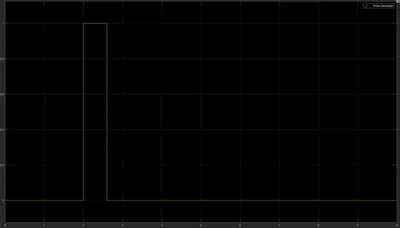
The above graph shows how the pulse is generated along the time period for 10 seconds.
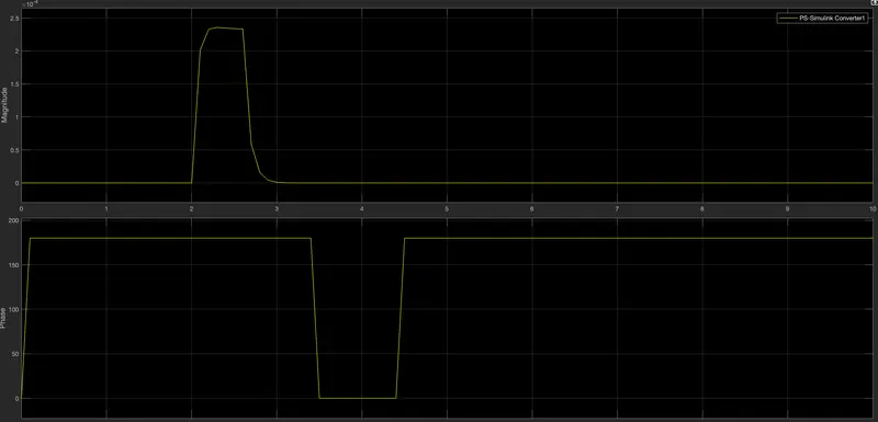
The above graph shows that the plunger dsiplacement where it moved at T=2 seconds and returned to the original position once the circuit is open again
2. Use a thermistor to sense the temperature of a heater & turn on or turn off the fan as per the below conditions:
Temperature source: 20 °C from 0 to 10 seconds, 27 °C from 10 to 30 seconds, 23 °C from 30 to 50 seconds
Fan conditions: ON if the temperature above 25 °C, OFF otherwise
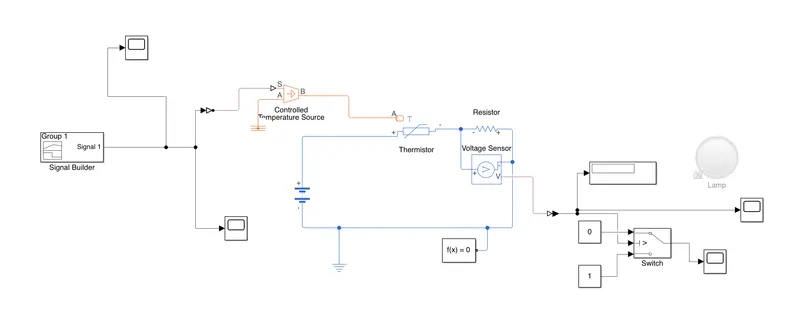
The following blocks are used
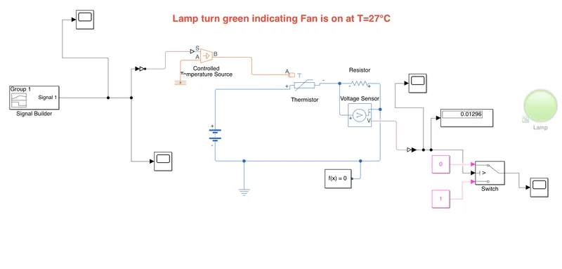
1. Signal Builder
2. Simulink to Physical signal converter
3. Controlled temperature source
4. Thermistor
5. Resistor
6. Voltage sensor
7. Lamp
8. Switch with constant blocks as input
9. Electrical reference
10. DC Voltage source
11. Solver configuration
12. Display and scope to view the results
1. Signal Builder: It is used to build your signals based on the input.
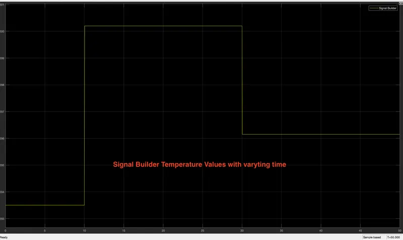
Here, X axis represents time, while Y axis represents temperature in Kelvin. The signals were adjusted manually based on the given input, that is for 10 seconds, T = 20° C(293.15k) 10 to 30 Secs, T = 27°C (300.15K) and from 30 to 50 secs, T = 23°C (296.15K).
2. Simulink to PS converter is used to convert the simulink signals to the corresponding physical signals which will be input to the controlled temperature source.
3. Controlled Temperature source:
This is an ideal energy source in a thermal network and can maintain a controlled temperature source regardless of the heat flow rate.Port S will receive the physical signal, while port A is connected to a thermal reference and port B connected to a thermistor
3. Thermistor:
Here a NTC thermsitor is used to identify the resistance across the circuit while the temperature changes. Port A receives the net heat flow in to the thermistor, while the postive and negative terminals are connected to a Battery.
4. Resistor is used to meaure the resistance in the thermistor due to temperature change
5. Voltage sensor: Voltage sensor is used to measure the voltage across the resistor
6. Electrical circuit:
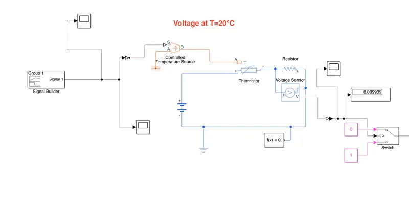
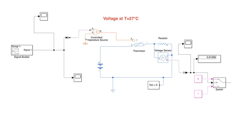
Battery, Thermistor, Resistor, Voltage sensor along with the electrical reference forms the electrical circuit
7. The V port from the voltage sensor is connected to PS to simiulink conveter and then to display to interpret the voltage value.
8. Switch: A switch is connected to the PS to simulink converter to read the voltage value based on the temperature change.
9. A Lamp is configured in such a way that it is connected to a switch which will indicate a threshold value based on which the lamp turns green when the fan is on and Red when the fan is off.
Working:
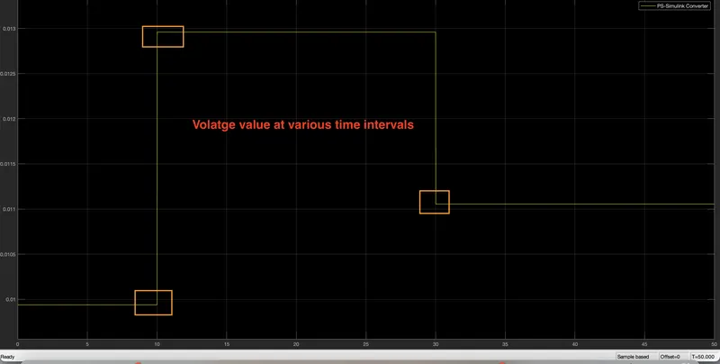
Initially the simulation is run for 10 seconds to identify the volatge at T = 20° C. The Below image represents that
Then the simulation is run for 30 seconds to identify the change in voltage across the resistor when T = 27°C
After which the simulation is run for 50 seconds to find the voltage at T = 23°C
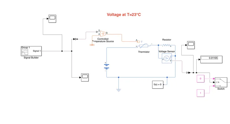
Based on the voltage values, the threshold value is found to be 0.012 greater than which the lamp will turn green and turn red otherwsie.