Week -2
Aim: Make a Simulink model of a Doorbell using a solenoid block with the following details.
In the above arrangement, when the switch is closed the electromagnet receives electrical power from the battery and pulls the metal arm to hit the bell producing sound.
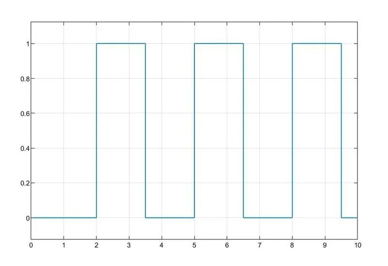
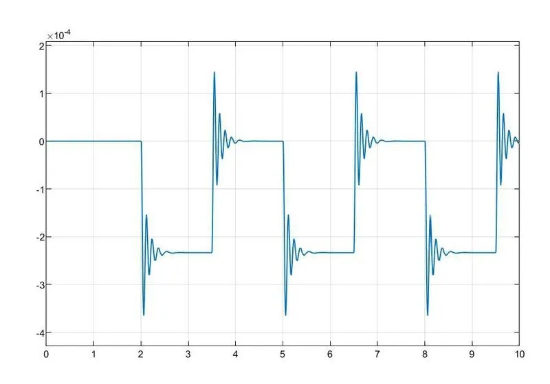
Create a situation where the switch is closed for 2 seconds and then released. Observe the physical movement of the plunger.
Explanation
A pulse generator block is used to create square waves at regular intervals. The output of the Pulse generator block is displayed using a scope.
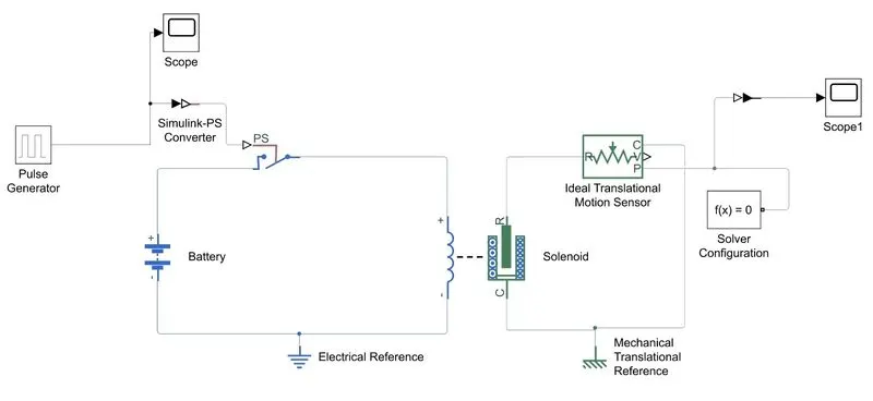
The ouput is connected to Simulink-Ps converter which is connected to the switch. The switch is connected to the positive terminal of the battery and the solenoid block. The electrical blocks are grounded to electrical resistance.
When the Pulse generator generates signals at alternate intervals, the translational motion of the solenoid is measured by connecting the Ideal translational motion sensor block which is connected to the R port of the solenoid.
The output from the Ideal translational motion sensor is connected to the Ps-Simulink converter and displayed in scope.
Blocks used:
Pulse Generator
The Pulse Generator block generates square wave pulses at regular intervals. The block waveform parameters, Amplitude, Pulse Width, Period, and Phase delay, determine the shape of the output waveform. The following diagram shows how each parameter affects the waveform.
Scope
The Simulink Scope block and DSP System Toolbox. Time Scope block displays time domain signals.
Simulink-PS Converter
The Simulink-PS Converter block converts the input Simulink® signal into a physical signal. Use this block to connect Simulink sources or other Simulink blocks to the inputs of a Simscape™ physical network.
Switch
A switch is controlled by an external physical signal. The Switch block models a switch controlled by an external physical signal.
Battery
The Battery block implements a generic dynamic model that represents most popular types of rechargeable batteries.
Electrical Reference
The Electrical Reference block represents an electrical ground. Electrical conserving ports of all the blocks that are directly connethe cted to ground must be connected to an Electrical Reference block. A model with electrical elements must contain at least one Electrical Reference block.
Solenoid
The Solenoid block represents the electrical characteristics and generated force for the solenoid in the following figure:
The return spring is optional. To remove the effects of this spring from the model, set the Spring constant parameter to 0.
Ideal Translational Motion Sensor
The Ideal Translational Motion Sensor block represents a device that converts an across variable measured between two mechanical translational nodes into a control signal proportional to velocity or position. You can specify the initial position (offset) as a block parameter.
The sensor is ideal since it does not account for inertia, friction, delays, energy consumption, and so on.
Connections R and C are mechanical translational conserving ports that connect the block to the nodes whose motion is being monitored. Connections V and P are physical signal output ports for velocity and position, respectively.
The block positive direction is from port R to port C. This means that the velocity is measured as v = vR – vC, where vR, vC are the absolute velocities at ports R and C, respectively.
Solver Configuration
Each physical network represented by a connected Simscape block diagram requires solver settings information for simulation. The Solver Configuration block specifies the solver parameters that your model needs before you can begin the simulation.
Each topologically distinct Simscape block diagram requires exactly one Solver Configuration block to be connected to it.
Mechanical Translational Reference
The Mechanical Translational Reference block represents a reference point, or frame, for all mechanical translational ports. All translational ports that are rigidly clamped to the frame (ground) must be connected to a Mechanical Translational Reference block.
Aim:
Use a thermistor to sense the temperature of a heater & turn on or turn off the fan as per the below conditions:
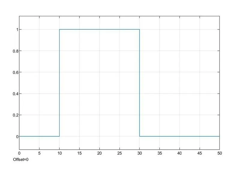
Temperature source: 20 °C from 0 to 10 seconds, 27 °C from 10 to 30 seconds, 23 °C from 30 to 50 seconds
Fan conditions: ON if the temperature above 25 °C, OFF otherwise
Explanation
A thermistor is a type of resistor whose resistance is strongly dependent on temperature, more so than in standard resistors.
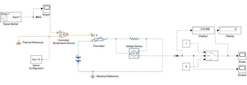
Condition: Input
0 to 10 sec -Temp-20 deg
10 to 30 sec-Temp-27 deg
30 to 50 sec-Temp-23 deg
Output
Fan on if the Temperatures rises above 25deg.
In order to achieve this condition, the voltage at 25degress is calculated by providing a constant value corresponding to 25 degree Celcius to the Thermistor.
This value is used as the Threshold value in the switch to fulfill the condition.
The range in temperature with respect to the time is achived using a Signal builder.
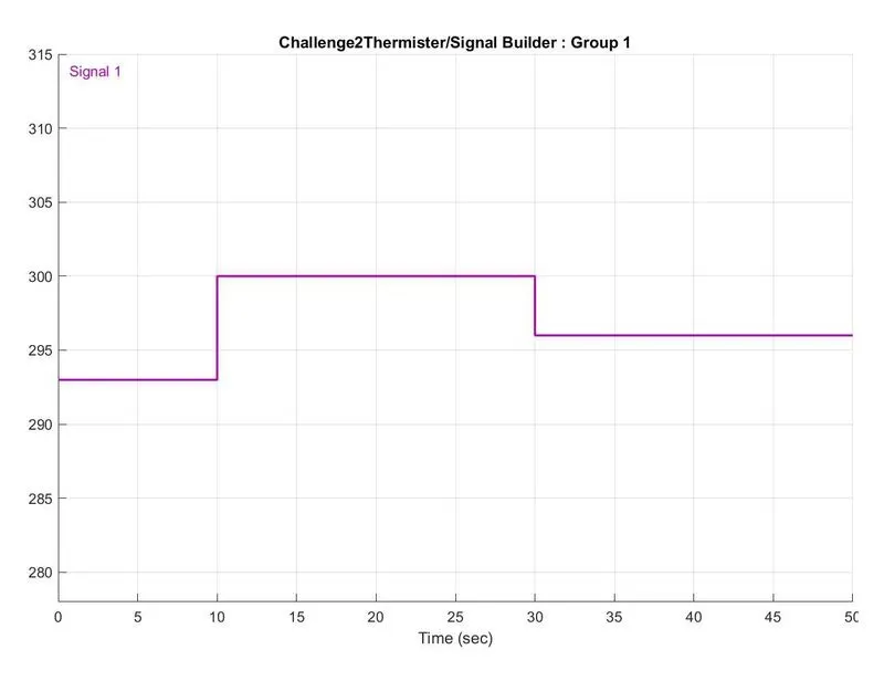
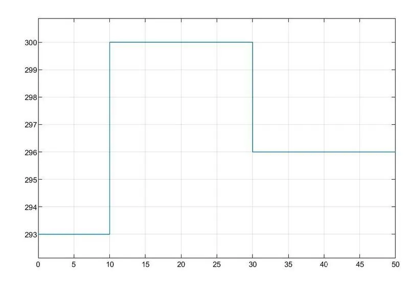
The switch Output scope clearly shows that Fan is ON from 10 to 30 seconds when the temperature is above 25 degress.