Week -2
Aim:-
- Make a Simulink model of Doorbell using solenoid block with the following details:
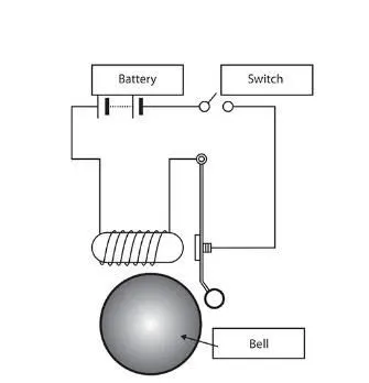
In the above arrangement, when the switch is closed the electromagnet receives electrical power from the battery and pulls the metal arm to hit the bell producing sound.
Create a situation where the switch is closed for 2 seconds and then released. Observe the physical movement of the plunger.
Assume remaining parameters.
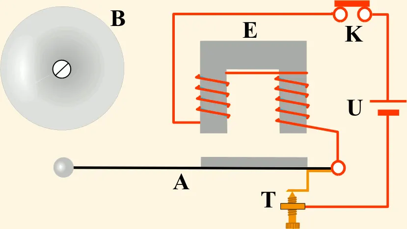
The above GIF file shows how the actual door bell works,When the switch is closed the electromagnet receives electrical power from the battery and pulls the metal arm to hit the bell producing sound.
~The Blocks which we haved used for the above Simulink models are :
- PULSE GENERATOR
- TWO SCOPE BLOCKS
- SIMULINK-PS CONVERTER
- SWITCH
- BATTERY
- ELECTRICAL REFERENCE
- SOLENOIDE
- IDEAL TRANSLATIONAL MOTION SENSOR
- MECHANICAL REFERENCE
- SOLVER CONFIGURATION
- PS-SIMULINK CONVERTER
- DISPLAY BLOCK
~Now we will learn what are its functions
1.PLUSE GENERATOR:--
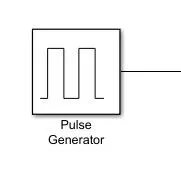
The Pulse Generator block generates square wave pulses at regular intervals. The block waveform parameters, Amplitude, Pulse Width, Period, and Phase delay, determine the shape of the output waveform. And it is shown in the below figure
2. SCOPE:--
The Scope block displays its input with respect to simulation time. The Scope block can have multiple axes, all axes have a common time range with independent y-axes. The Scope allows you to adjust the amount of time and the range of input values displayed.And it is shown in the below figure
3.SIMULINK-PS CONVERTER:--
Converts the Simulink input signal to a Physical Signal.
4.SWITCH:--
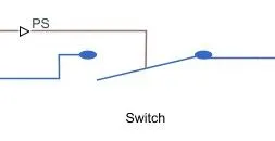
The block represents a switch controlled by an external physical signal. If the external physical signal PS is greater than the threshold, then the switch is closed, otherwise the switch is open.
5.BATTERY :--
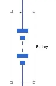
This block models a battery. If you select Infinite for the Battery charge capacity parameter, the block models the battery as a series internal resistance and a constant voltage source. If you select Finite for the Battery charge capacity parameter, the block models the battery as a series internal resistance plus a charge-dependent voltage source defined.And the Block diagram is shown in the below figure.
6.ELECTRICAL REFERENCE:--
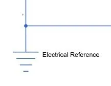
Electrical reference port. A model must contain at least one electrical reference port (electrical ground).The below figure shows the electrical reference
7.SOLENOIDE:--
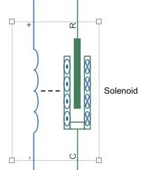
This block implements the electrical and mechanical characteristics of a solenoid. Parameterization is in terms of two points [X1,F1] and [X2,F2] on its force-stroke curve for a 100 percent duty cycle at Rated voltage Vdc and Rated current Idc where X2>X1>0 are stroke values and F1>F2>0 are corresponding forces. The plunger fully in (i.e. air gap closed) corresponds to X=0, and pull-in force is assumed to decrease quadratically with the magnitude of X. To ensure the force remains finite, the following condition should hold: X2/X1>sqrt(F1/F2).
8.IDEAL TRANSLATIONAL MOTION SENSOR:--
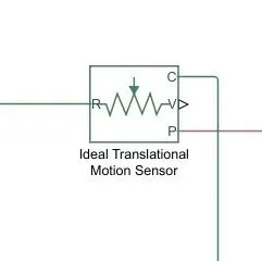
The block represents an ideal mechanical translational motion sensor, that is, a device that converts an across variable measured between two mechanical translational nodes into a control signal proportional to velocity and position. The sensor is ideal since it does not account for inertia, friction, delays, energy consumption, and so on.
Connections R and C are mechanical translational conserving ports and connections V and P are physical signal output ports for velocity and position, respectively. The block positive direction is from port R to port C.
And the below figure shows ideal translational motion sensor block.
9.MECHANICAL REFERENCE:--
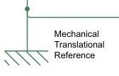
Mechanical reference block represents a mechanical translational reference point, that is, a frame or a ground. Use it to connect mechanical translational ports that are rigidly affixed to the frame (ground).
10.SOLVER CONFIGURATION :--
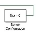
Simulink provides a set of programs called solvers. Each solver embodies a particular approach to solving a model. A solver applies a numerical method to solve the set of ordinary differential equations that represent the model.it will be fixed solver or it will be variable solver,And the below block represents the solver block
11.PS-SIMULINK CONVERTER:--
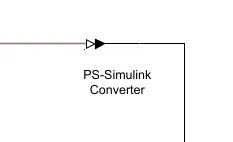
It Converts the input Physical Signal to a Simulink output signal.
12.DISPLAY:--
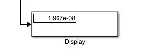
Display input values. If the incoming signal is of type string, the 'Numeric display format' parameter selection does not affect the display of the string.
~A Simulink model of Doorbell using solenoid block is shown below (input)
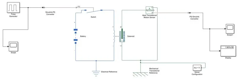
~output1:-
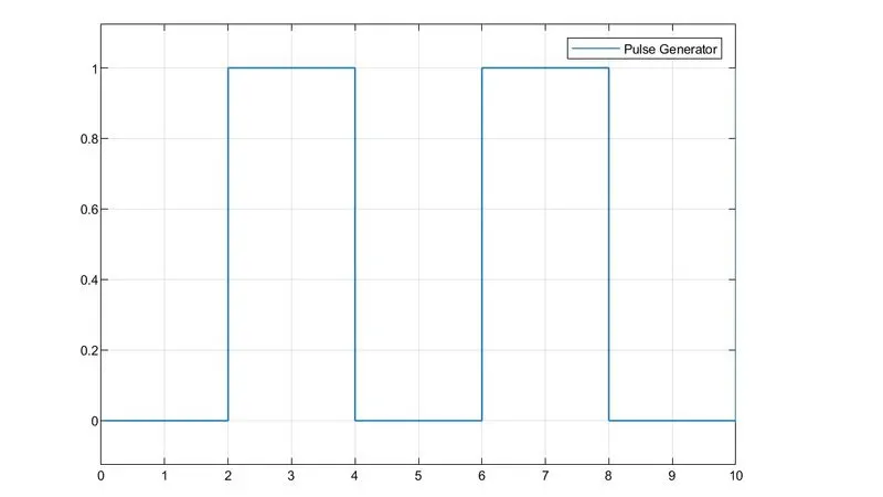
~output2:-
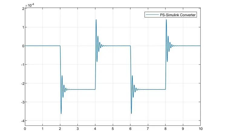
~Answer for question 2:-
Aim:-
Use a thermistor to sense the temperature of a heater & turn on or turn off the fan as per the below conditions:
~Temperature source:
20 °C from 0 to 10 seconds,
27 °C from 10 to 30 seconds,
23 °C from 30 to 50 seconds
~Fan conditions:
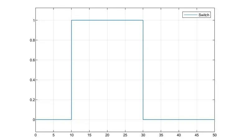
ON if the temperature above 25 °C, OFF otherwise
What is Thermistor ?
A thermistor was first discovered by Michael Faraday in 1833 on a silver sulfide which showed a behavior of decrease in resistance when temperature increased.
"A thermistor is a semiconductor that has a resistance capacity more than a conducting material and less than insulating material".
Its electrical resistance varies with the change in the temperature There are mainly two types of thermistors,namely the Negative Temperature Coefficient (NC) and the Positive Temperature Coefficient (PTC).
Thermistor's relation with temperature also depends on the material in which it is made. A negative temperature coefficient (NTC) thermistor will decrease its resistance value when temperature increases whereas a Positive temperature coefficient will increase its resistance when temperature increases. The electronic symbol of the thermistor is given below
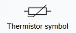
NTC thermistors are widely used in industries for different applications like temperature measurements, temperature control, and different applications NTC is an integral part of. PTC is mostly seen in circuit protection, current-limiting resistors.
Thermistors have high sensitivity which can be up to 10 percent change per degree celsius and their typical response time is 0.5 to 5s with an operating range from -50 to ~300 °C and there are devices with more capacity.
~ Use a thermistor to sense the temperature of a heater & turn on or turn off the fan as per the below conditions:
~Temperature source:
20 °C from 0 to 10 seconds,
27 °C from 10 to 30 seconds,
23 °C from 30 to 50 seconds
~Fan conditions:
ON if the temperature above 25 °C, OFF otherwise
Input :--
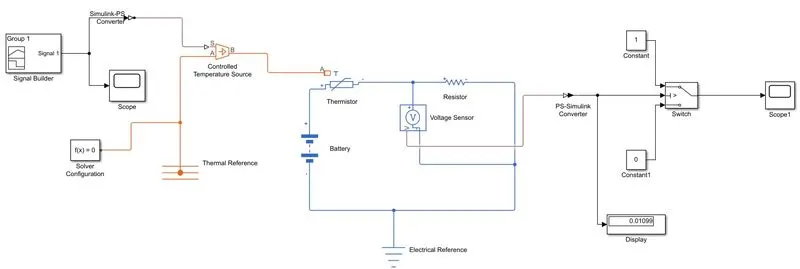
~The Blocks that are used in the above simulation is :--
*singnal builder
*scope
*solver configuration
*simulink ps converter
*controlled temprature source
*Thermal reference
*Thermistor
*Battery
*Resistor
*voltage sensor
*Electrical reference
*ps- simulink converter
*Constant
*Switch
*Display
~Output:--
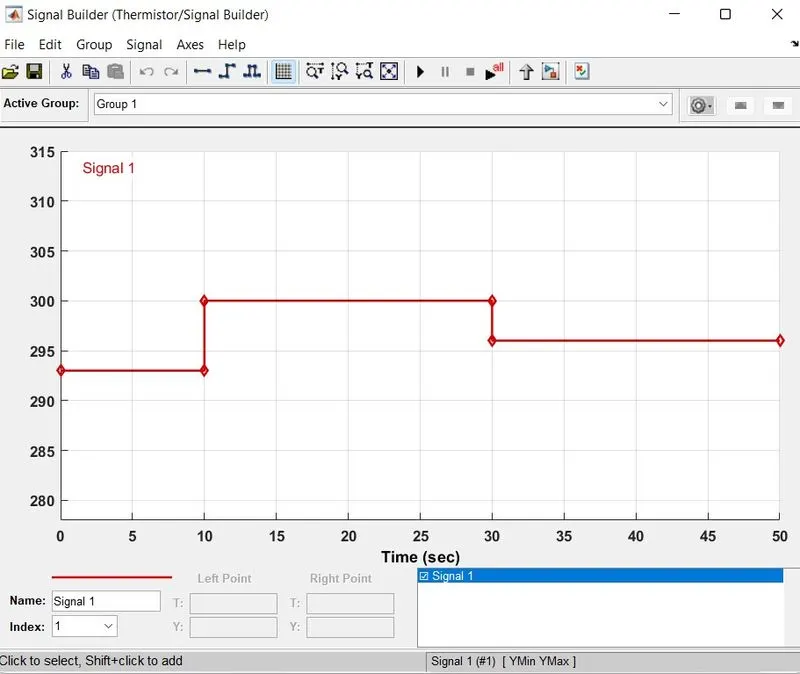
~Signal Builder Block :--
~Temperature source:
20 °C from 0 to 10 seconds,
27 °C from 10 to 30 seconds,
23 °C from 30 to 50 seconds
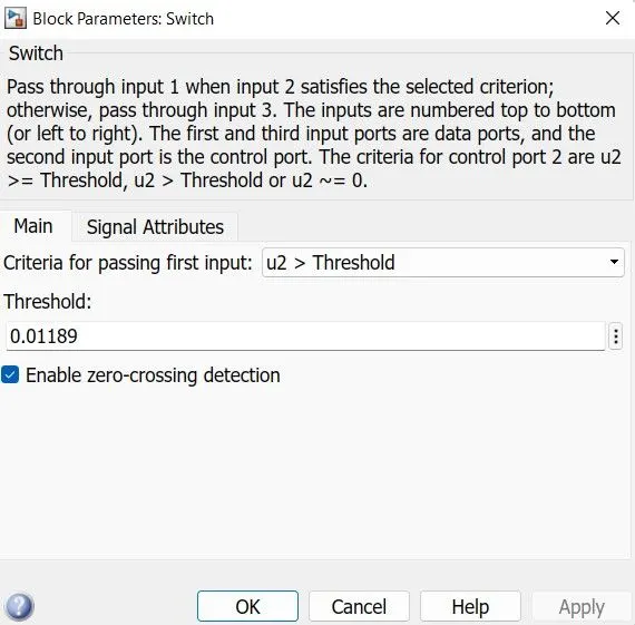
~And we have to change the Threshold Value
~And we have to change the time to 50sec and it shown in the below figure,since we have used time limit as 50