Week -2
Aim:-
To make a simulation model of a doorbell using solenoid block.
To use thermistor to sense the temperature of a heater and turn on & turn off the fan.
Objective:-
1.Make a Simulink model of Doorbell using solenoid block with the following details:
Create a situation where the switch is closed for 2 seconds and then release. Observe the physical movement of the plunger.
2. Use a Thermistor to sense the temperature of a heater and turn on & turn off the fan as per the below condition:
Temperature source: 20°C from 0 to 10 seconds, 27°C from 10 to 30 seconds, 23°C from 30 to 50 seconds
From condition:ON the temperature above 25°C, OFF otherwise.
Solution:
1.Here first we are going to study the simulink model of the doorbellu sing a solenoid block.
Doorbell:-
A doorbell is a signaling device typically placed near a door to a building entrance. When a visitor presses a button the bell rings inside the building, altering the accupant to the presence of the visitor. The heart of a doorbell is an electromagnet. Electromagnet are a coil of wire wrapped around a small piece of magnetic metal. When electricity passes through the wire, it creates a magnetic field around the wire. When you press a doorbell button, you complet an electrical circuit that allows household electricity to flow through the doorbell's internal electromagnet. The magnetic field generated by the electromagnet is then used to power a mechanism that creates the doorbell sound.
A chime doorbell uses a specialized sort of electromagnet called a solenoid. The tone of the sound generated depends on the shape and size of the bell resonator. Where several bells are install together, they may be given distinctive ring by using different size or shape of bell, even though the strike mechanism are identical.
Solenoid:-
A solenoid is a device comprised of a coil of wire, housing and a movable plunger. When an electrical current is introduce, a magnetic field forms around the coil which drows the plunger in. More simply, a solenoid converts electrical energy into mechanical work. The coil is made of many turns of tightly wound copper wire. When an electrical current flows through this wire, a strong magnetic field or flux is creaated.
Electromagnetic induction makes it on electromagnet that can be switch on or off. The side in which the current appears to be passing clockwise is the South pole, and the side in which the current seems to be passing anticlockwise is the Northern pole. The solenoid works just like a bar magnet and therefore has many uses. This principle is used to create volves, among other things. Where the solenoid operates an electric switch,it is a relay.
Simulink Model:
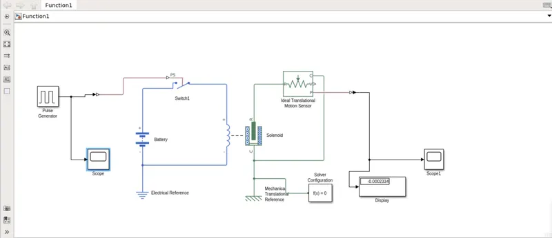
The Above figure is representation of "A doorbell on solenoid". In this model some blocks are used to make the working model of the doorbell.
Pulse Generator: The pulse generator block generates square wave pulse at regular intervals. The block waveform parameters, Amplitude, Pulse width, Period and Phase delay, determine the shape of the output waveform.
Simulink-PS Converter: Converts the unitless Simulink input signal to a physical signal.
Scope: Display signal generated during simualation.
Switch: Switch controlled by an exeternal physical signal.
Battery: The battery block represents a simple battery model.
Solenoid: Model electrical characteristics and generated force of solenoid.
Ideal Translational Motor Senser: The ideal translational motor senser block represents a device that converts an across variable measured between two mechanical translational nodes into a control signal proportional to velocity or position. You can specify the initial position (offset) as a block parameter. The senser is ideal since it does not account for inertia, friction, delays, energy consuption, and so on.
Mechanical Translational Refference: The Mechanical Translational Refference block represent point or frame, for all mechanical ports. All translational ports that are rigidly clamped to the frame must be connected to a mechanical translational refference block.
Electrical Refernce: The Electrical Refference block represents an electrical ground. Electrical conserving ports of all the blocks that are directly connected to the ground must be connected to an electrical refference block. A model with electrical element must contain at least one electrical refference block.
Solver Configuration: The Solver Configuration block specialise the solver parameters that your models need before you can begin the simulation.
PS-Simulink Converter: Convert physical signal into Simulink output signal.
Model Explanation:-
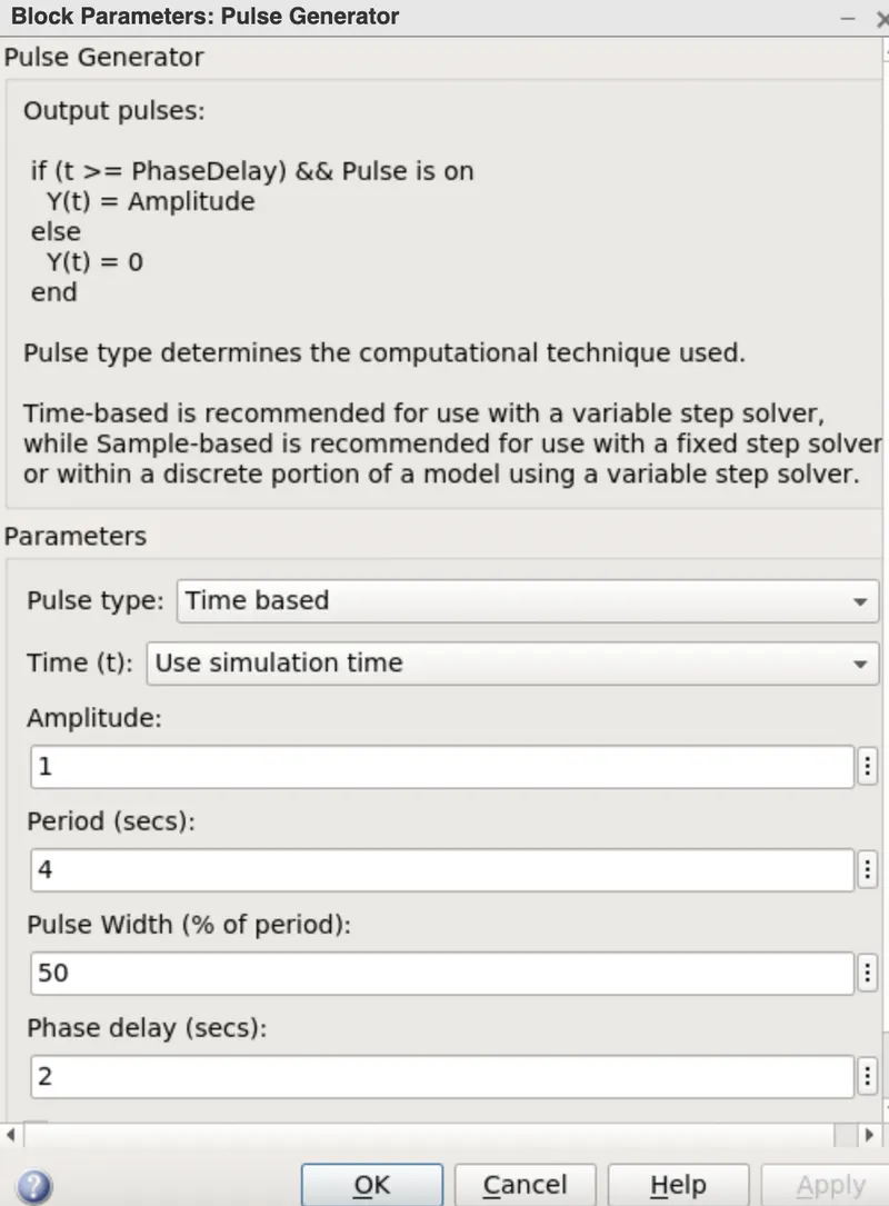
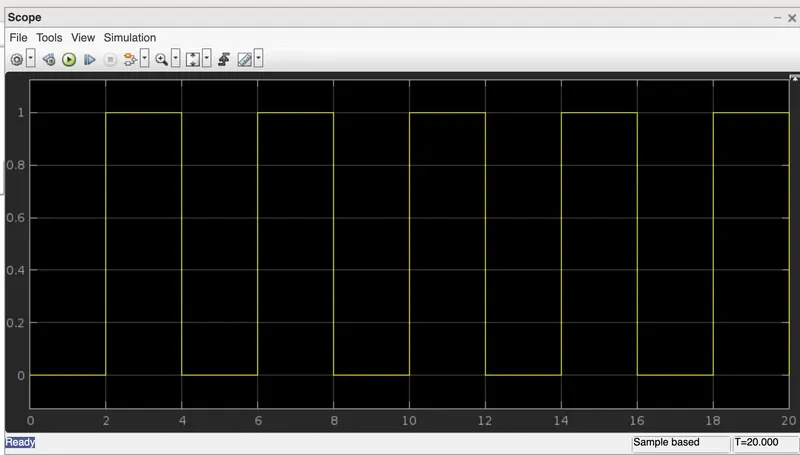
- The Pulse generator block is used to give signal input like amplitude, pulse width and phase delay to determine the shape of the output length. Scope is used to see the graph of wavelenght.
- The pulse generator block is give the signal input where, Amplitude =1sec,Peroid=4sec,Pulse width=50% and phase delay=2sec.
- The switch block used is controlled by exeternal physical signal. If the exeternal signal is greater than the thresold parameter then the switch is closed , otherwise switch is open.
- After that input signal is converted into a physical form with the use of "Simulink-PS converter" and further send to the switch of the elctrical circuit.
- The electric circuit consist of a solenoid, battery, and a switch. One end of the solenoid is connected to the battery and other end is connected to the switch. An electrical refference is provided in the electrical circuit.
- The mechanical part of the solenoid is connected to an Ideal Translationa motion senser and Mechanical Translational refference.
- The P port of the senser makes a connection of this converter to provide the output in signal form, the converter is connected to the scope to display our output signal. The solver configuration block is used to specify the solver parameter.
Scope: Input Signal of Pulse generator
Output:-
Scope1:
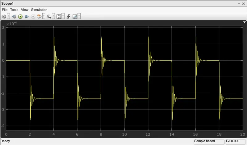
In the above graph we can see that switch is closed for 2 second after that switch is open. Amplitude is equal to 0 means the switch is closed. We can also see the plunger strike is every 2 seconds.
2. Use a Thermistor to sense the temperature of a heater & turn on or off the fan as per the below conditions:
We going to use the same procedure as above to simulate the thermistor to sense the temperature of a heater.
Thermistor:
Thermistor or Thermal registor is defind as a type of registor whose electrical resistance varies with changes in temperature. Although all resistor resistance will fluctuate slightly with temeprature, a thermistor is perticularly sensitive to temperature.
The thermistor is its dependency on resistance values on the change in temperature. The value of regisstance can be measured by using an ohmmeter, these are connected in series with the battery.
Thermistor acts as a passive component in a circuit. They are an accurate, cheap and robust way to measure temeprature. While thermistor do not work well in extremely hot or cold temepratures, they are the senser of choice for many different applications.
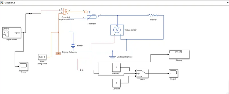
Simulink Model:-
Model Explanation:-
- The input signal is generated with the help of a signal builder block, the signal is created in signal builder and further passes to simulink-PS converter to convert the input signal into the physical signal.
- Controlled temperature source represents an ideal source of thermal energy, that can maintain a controlled temperature difference regardless of the heat flow rate.
- Thermistor is type resistor whose resitance is based upon temerature. The voltage senser is used to convert the voltage measured between two point into a physical signal.
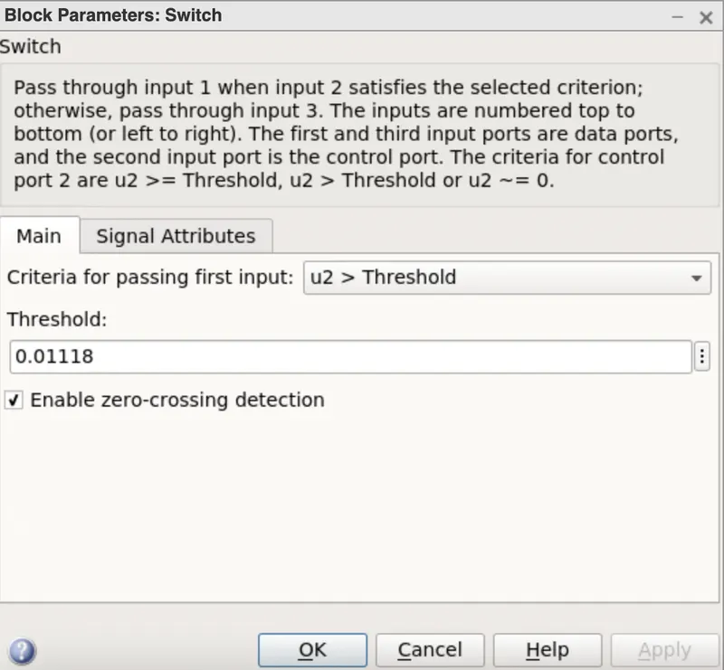
- In the above simulink model representation of Thermistor connection which senses the temperature of a heater and passes the signal to a switch where a thresold limit is already set. If the temperature is above or equal to the thresold limit, thenit gives 1 as output which is switch on. If the temperature below the thresold limit, then it will give 0 as output which means switch off.
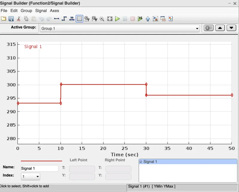
- In signal builder we created an input signal for system.The condition are as follow:
From 0-10 sec temperature is 293.15 K (20°C)
From 10-30 sec temperature is 300.15 K (27°C)
From 30-50 sec temerature is 296.15 K (23°C)
For condition: ON if the temperature above 25°C, OFF otherwise.
- Here the temperature is converted in Kelvin from degree celcius becouse of the signal converter does not take °C value as a input.
- After running for 50 sec we nedd to provide the display as an input to the switch for On and Off condition.
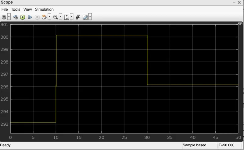
At the end of the system scope is connected to see output for the fan on or off condition. We run the simulation for
50 seconds becouse we take time limit in signal builder in 50 sec, so we can get the following output.
Output:-
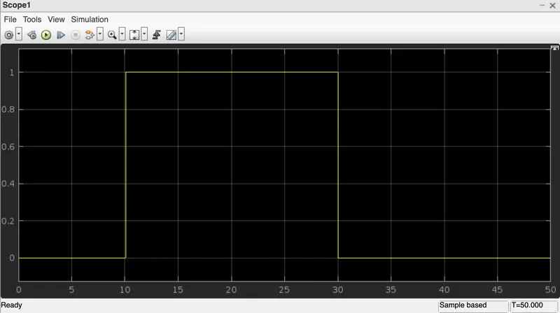
The value of the signal is 0 form 0 to 10 sec fan is OFF condition because temperature is 293.15 K which is below thresold 298.15 K. After the signal value is 1 as output from 10 to 30 sec temperature goes to 300.15 K then the switch will be in ON conditionas the temerature exceeds 298.15 K. After 30 sec the value of signal is agnain 0 from 30 to 50 sec fan will turn OFF as the temperature comes down to 296.15 K which is below the thresold temperature of 298.15 K.
Conclusion:-
1.From the above output results that we have successfuly simulated doorbell mechanism operated by solenoid with given condition.
2.We can conclude that from the above output results of our simulink model for solenoid operated heaters gives correct output.