Project
AIM:
To carry out a system-level simulation of an all-terrain vehicle using Simulink.
KEYWORDS:
CVT, Lookup Table, Dashboard, BAJA ATV
OBJECTIVE:
To Prepare a technicle report of BAJA ATV model properties for with and without lookup table.
THEORY:
All TERRAIN VEHICLE:
An All-Terrain Vehicle (ATV) as defined by the American National Standards Institute (ANSI), is a vehicle that travels on low-pressure tires, with a seat that is staddled by the operator, along with handlebars for steering control. It is designed to handle a wider a variety of terrain than most other vehicles.
BAJA ATV:
The BAJA ATV series is an event for the undergraduate engineering students, organised globally by the Society Of Automotive Engineers, USA. The event originated in the name of Mini-BAJA, in the year 1976 at University of Caroline. Since then, the event has spanned across six countries-USA, Mexico, South Africa, Korea, Brazil and India. The BAJA ATV Tasks The students to design, fabricate and validate a single seater four-wheeled off road vehicle to take part in series of events spread over a course of three days that test the vehicle for the sound engineering practices that have gone into it, the ability of the vehicle in termes of gradeability, speed, acceleration, and maneuverability characteristics and finallly its ability to endure that back breaking durability test.
MAJOR COMPONENTS IN THIS SIMULATION:
SIGNAL BUILDER:
The Signal Builder block allows you to create interchangeable groups of piecewise linear signal sources and use them in a model. You can quickly switch the signal groups into and out of a model to facilitate testing.
GENERIC ENGINE:
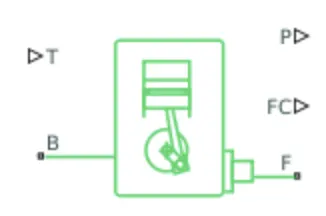
The generic engine block represents a general Internal Combution (IC) Engine, which is a type of Spark Ignition(SI-Petrol) or Compression Ignition (CI-Diesel). The speed torque and speed power parameter are provided.
The throttle input signal T lies between zero and one and specifies the torque demanded from the engine as a fraction of the maximum possible torque. The Connection F and B are mechanical rotational conserving ports associated with the engine crackshaft and engine block, respectively. Connection P and FC are physical signal output ports through which engine power and fuel consumption rate are reported.
ENGINE SENSOR:
Ideal Rotational Motion Sensor:-
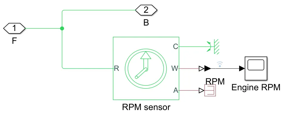
The block represents an ideal mechanical rotational motion sensor, that is, a device that converts an across variable measured between two mechanical rotational nodes into a control signal proportional to angular velocity or angle. The sensor is ideal since it does not account for inertia, friction, delays, energy consumption, and so on.
Connections R and C are mechanical rotational conserving ports and connections W and A are physical signal output ports for velocity and angular displacement, respectively.
SIMPLE GEAR:
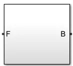
The simple gear is a combination of a driver and driven gear where the speed is reduced by the gear ratio. Represents a fixed-ratio gear or gearbox. No inertia or compliance is modeled in this block. You can optionally include gear meshing and viscous bearing losses.
Connections B (base) and F (follower) are mechanical rotational conserving ports. Specify the relation between base and follower rotation directions with the Output shaft rotates parameter.
VARIABLE TRANSMISSION RATIO:
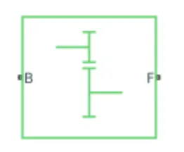
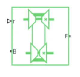
Represents a variable ratio gearbox such as implemented by mechanical belt CVT, electric, or hydraulic transmissions. The physical signal input r defines the ratio of input to output angular shaft velocities.
Connections B (base) and F (follower) are mechanical rotational conserving ports. Specify the relation between base and follower rotation directions with the Output shaft rotates parameter.
CONTINUOUS VARIABLE TRANSMISSION (CVT):
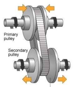
It is better to have more gears in a transmission, since it can optimize engine speed in a variety of driving conditions. That means low gears can provide better acceleration while higher gears can maximize fuel economy. CVTs differ from traditional automatic transmissions in that they don't have gears that provide "steps" between low- and high-speed operations. Instead, the majority of them work via a pair of variable-diameter, cone-shaped pulleys connected by a steel or composite belt. The halves of each pulley are aligned with the pointed ends of the cones touching. These form a V-shaped groove in which the connecting belt rides. One side of the pulley is fixed, and the other side is movable, actuated by a hydraulic cylinder. The cylinder can increase or decrease the amount of space between the two sides of the pulley. This allows the belt to ride lower or higher along the walls of the pulley, depending on driving conditions, thereby changing the "gear" ratio.
VEHICLE BODY:
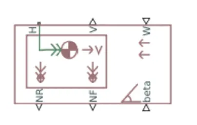
Two – axle vehicle with longitudinal dynamics and motion and adjustable mass, geometry, and drag properties. The vehicle can have the same or a different number of wheels on each axle. For example, two wheels on the front axle and one wheel on the rear axle. The vehicle wheels are assumed identical in size. The vehicle can also have a center of gravity (CG) that is at or below the plane of travel.
Connection H is the mechanical translational conserving port associated with the horizontal motion of the vehicle body. The resulting traction motion developed by tires should be connected to this port. Connections V, NF, and NR are physical signal output ports for vehicle velocity and front and rear normal wheel forces, respectively. Wheel forces are considered positive if acting downwards. Connections W and beta are physical signal input ports corresponding to headwind speed and road inclination angle, respectively. If the variable mass is modeled, the physical signal input ports CG and M are exposed. CG accepts a two-element vector representing the x and y distance offsets from vehicle CG to additional load mass CG. M represents the additional mass. If both variable mass and pitch dynamics are included, the physical signal port J accepts the inertia of the additional mass about its own CG.
DOUBLE-SHOE BRAKE:
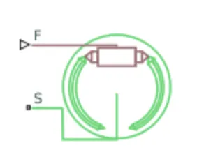
The Double-Shoe Brake block represents a frictional brake with two pivoted rigid shoes that press against a rotating drum to produce a braking action. The rigid shoes sit inside or outside the rotating drum in a diametrically opposed configuration. A positive actuating force causes the rigid shoes to press against the rotating drum. Viscous and contact friction between the drum and the rigid shoe surfaces cause the rotating drum to decelerate.
TIRE:
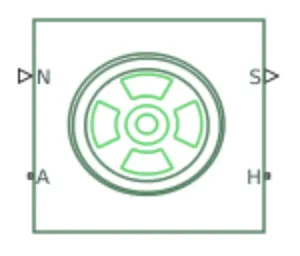
Represents the longitudinal behavior of a highway tire characterized by the tire Magic Formula. The block is built from Tire-Road Interaction (Magic Formula) and Simscape Foundation Library Wheel and Axle blocks. Optionally, the effects of tire inertia, stiffness, and damping can be included.
Connection A is the mechanical rotational conserving port for the wheel axle. Connection H is the mechanical translational conserving port for the wheel hub through which the thrust developed by the tire is applied to the vehicle. Connection N is a physical signal input port that applies the normal force acting on the tire. The force is considered positive if it acts downwards. Connection S is a physical signal output port that reports the tire slip. Optionally expose physical signal port M by setting Parameterize by to Physical signal Magic Formula coefficients. Physical signal port M accepts a four-element vector corresponding to the B, C, D, and E Magic Formula coefficients.
INERTIA:
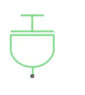
The block represents an ideal mechanical rotational inertia.The block has one mechanical rotational conserving port. The block positive direction is from its port to the reference point. This means that the inertia torque is positive if the inertia is accelerated in a positive direction.
BLOCKED USED:
- Signal Builder – To input the Brake, Throttle and CVT Ratio.
- Simulink to PS converter – To convert the Simulink signal to Simscape environment.
- Solver Configuration – To specify the solver parameters before starting the simulation.
- Mechanical Reference – To make sure all the components are clamped to the ground.
- Generic Engine – To run the engine with speed and torque values as input.
- PS to Simulink Converter – To convert Simscape signal to Simulink environment.
- Scope – To view the graph of the parameters for better understanding.
- Inertia – To represent the solid inertia.
- Rotational Motion Sensor – To sense the rotational motion from the engine and give output as RPM.
- Variable Ratio Transmission – To vary the speed according to the gear ratios.
- PS Terminator – Terminator for unconnected physical signal outputs.
- Double Shoe Brake – To apply brake to the vehicle when needed.
- PS Constant – Generate constant physical signal.
- Tire – For transportation of the vehicle.
- Rotational Free End – For mechanical component (Tire)
- Vehicle Body – To represent the BAJA ATV model body.
- Custom Measure Gauge – To measure the brake and throttle input.
- Knob – To increase, decrease and vice-versa of throttle and brake inputs.
- Lookup Table – To insert the CVT values from the workspace.
- Simple Gear – To reduce the speed of the engine with pre-defined gear ratio.
- Step – To increase or decrease an input value for a defined time interval.
STUDY1:
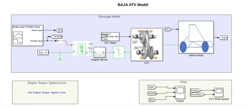
BAJA ATV Model without dashboard:
CVT SUBSYSTEM:
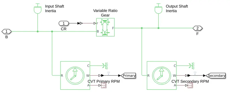
Input shaft represents the primary pulley and output shaft represents the secondary pulley and mechanical rotational sensor is connected to input and output shafts and Variable ratio Gear represents a variable ratio gearbox such as implemented by mechanical belt CVT, electric, or hydraulic transmissions. The physical signal input r defines the ratio of input to output angular shaft velocities.Connections B (base) and F (follower) are mechanical rotational conserving ports. Specify the relation between base and follower rotation directions with the Output shaft rotates parameter. Here CVT ratio is generated by Signal Builder.
VEHICLE BODY SUBSYSTEM: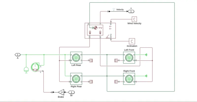
Brake and Throttle input:
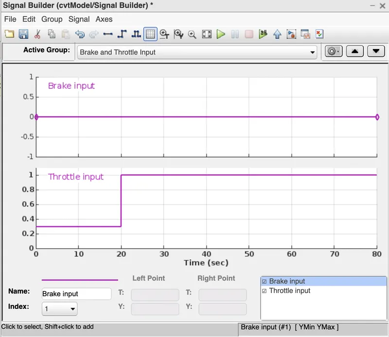
The input signal is provided using signal builder in which brake input is provided as 0 and trottel input is provided as 0.3 upto 20sec and varied to 1 for remaining seconds.
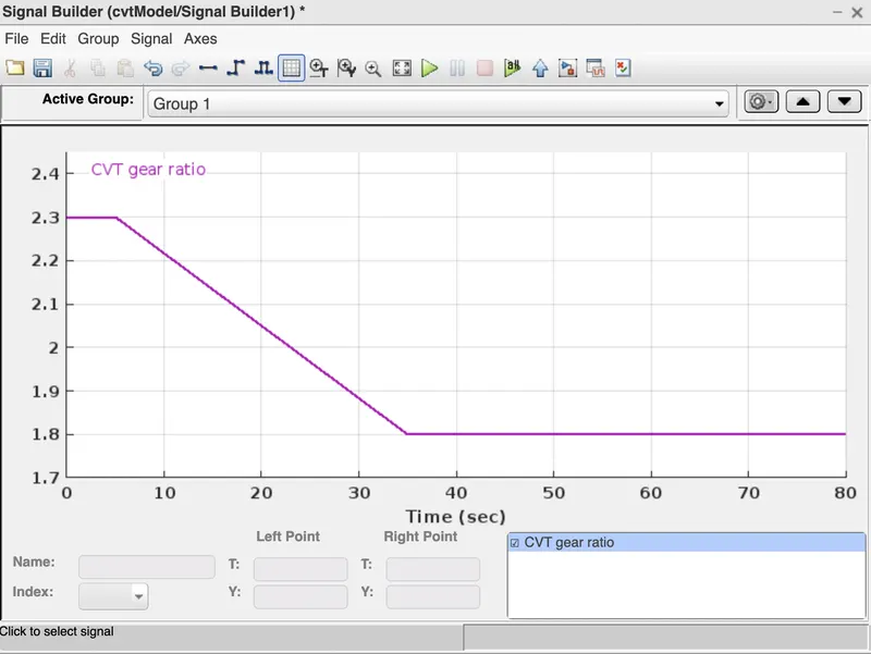
The CVT gear ratio is maintained as 2.3 for 5 secs and linearly decreases to 1.8 and maintained constant for remaining seconds.
Toeque vs Engine Speed input:
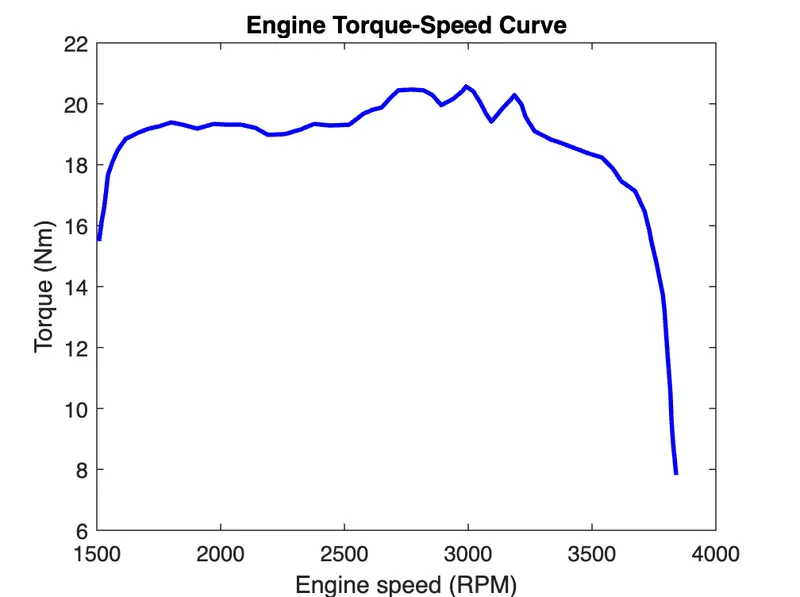
Output:
Vehicle Speed-
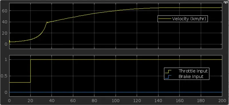
In the above result we can see that, the brake is maintained as constant and when we increasing throttle the velocity is increasing And after certain time it is using the maximum velocity and then remain constant. The brake input value is zero is no effect on velocity.
CVT Shaft Speed-
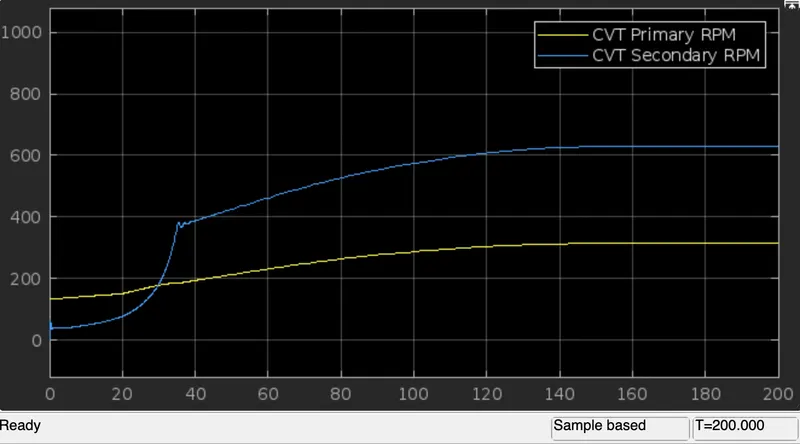
In this result shows the variation in angular velocities of input and output shaft of the variable gear transmission system. The secondary shaft reaches high speed and primary shaft as low rotational speed becouse of the secondary shaft as more than the primary shaft.
STUDY2:
BAJA ATV Model with dashboard:-
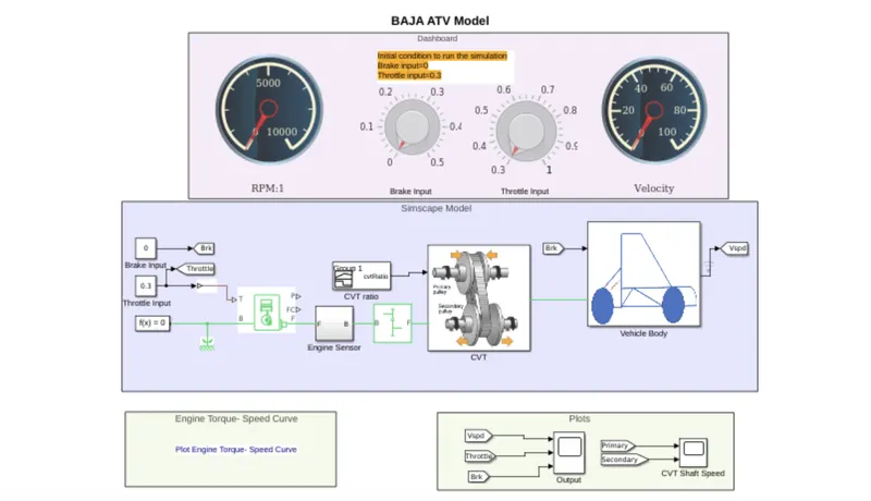
The study is based on 'BAJA ATV with dashboard' as shown in the above model here input data like trottel and brake input is given from the dashboard instead of providing the signals through signal builder and all the remaining blocks are same.The main purpose of using dashboard is to study the output value with the variation of input data of throttle and brake in the digital reading.
Output:
Vehicle Speed-
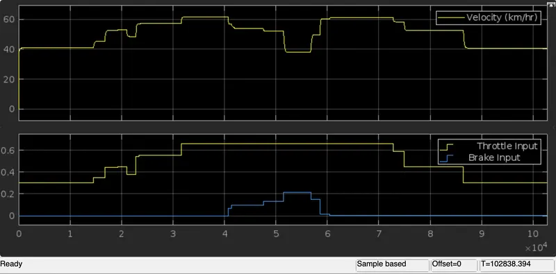
In above result we see , the velocity of vehicle increasing drastically from 0 to 40 kmph, the velocity is maintained as constant for constant trottle value as 0.3 and varying by increasing the value of throttle ,the velocity of vehicle is increses. When we increasing brake input ,the velocity of the vehicle decreasing.
CVT Shaft Speed-
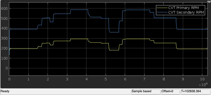
In the above result We see that, the primary shaft speed increases by changing throttle and increasing brake input the shaft speed decreasing. Which defines that the trottle can flow more amount of fuel which increase the power of the engine and similar to the secondary shaft.The trottle value and brake value can be varying in dashboard , so we can get any particular value for input.
STUDY3:
BAJA ATV Model without dashboardusing lookup table:
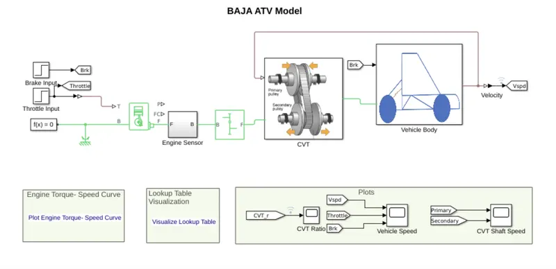
The above model of Baja ATV with CVT along with the lookup table is similar to the previous model which includes generic engine, CVT, simple gear, engine sensor, Vehicle body the only difference is that the CVT ratio is provided in lookup table.
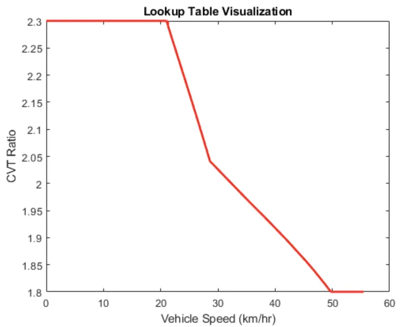
Lookup table-
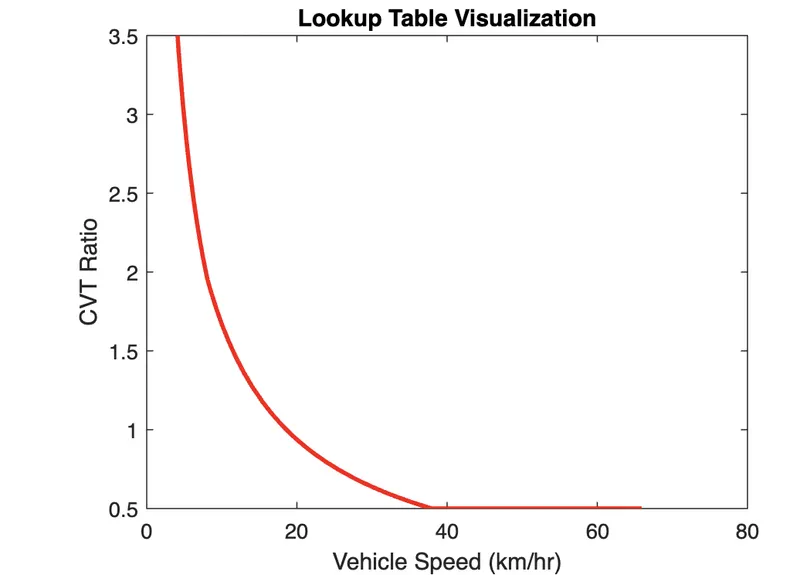
A lookup table is an array of data that maps input values to output values, thereby approximating a mathematical function. Given a set of input values, a lookup operation retrieves the corresponding output values from the table. If the lookup table does not explicitly define the input values, simulink can estimate an output value using interpolation, extrapolation, or rounding.
where:
- An interpolation is a process for estimating values that lie between known data points.
- An extrapolation is a process for estimating values that lie beyond the range of known data points.
- A rounding is a process for approximating a value by altering its digits according to a known rule.
CVT SUBSYSTEM:
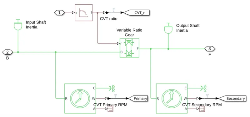
In above CVT Subsystem is same as First Subsystem. Here CVT ratio is obtained from the lookup table.
VEHICLE BODY SUBSYSTEM:
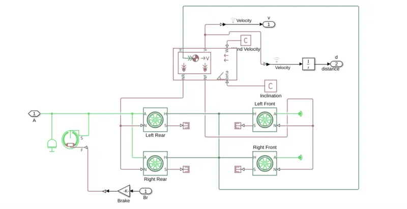
The brake input and throttle input is given by step time, which depends on the run time and varies accordingly. By using Lookup table for gear ratio which takes as input to the CVT and works according to the input gear ratio and obtained the output. This method is very effective which can avoid the unusual torque at the certain speed and very easy to achieve greater velocity & engine speed. It works as closed loop when the input is given by lookup table. The simulink get the input value from lookup table and obtain the result according to the input values of gear ratio. The gear ratio varies from 2.3 to 1.8 as taken as input and output interms of velocity.
Output:
Vehicle Speed-
In the above result we can see that brake input is maintained as constant and we when increasing the trottle input the velocity is increasing and after certain time it is maximum velocity and the flow of fuel is increases when the throttle increases from 0.3 to 1, thus the power in engine increases. The gear ratio is assigned the lookup table and to gives the input to the simulink.
CVT Shaft Speed-
In the above result, the CVT gear ratio falls below 1 (at about 28 sec), the secondary RPM becomes higher than the primary RPM as the velocity of the vehicle also increases with the reduction in torque.
CVT Ratio-
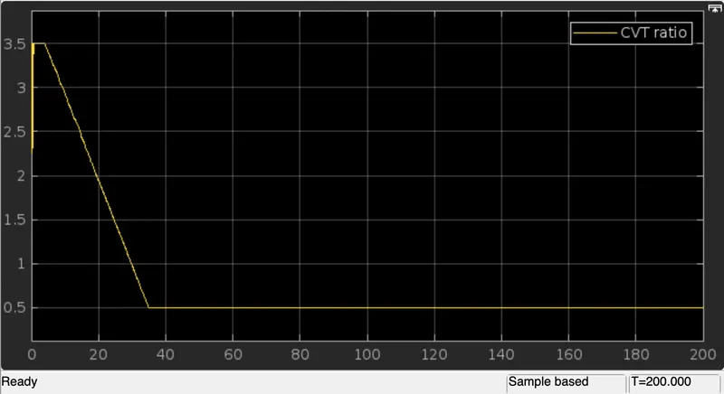
The above data is obatained from the lookup table.
STUDY4:
BAJA ATV Model with dashboard using lookup table:
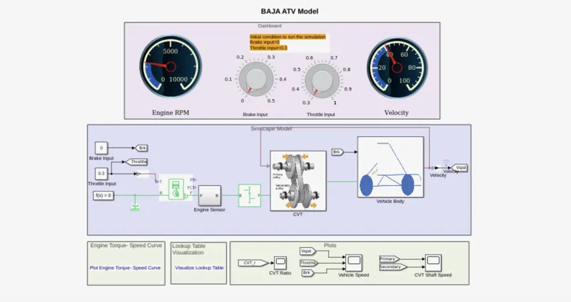
Baja ATV with dashboard model using lookup table which consists throttle meter and brake input in the dash board and indicated as constant block. Rest of the blocks and subsystems are common in the above baja ATV model without dash board. The main concept of using dash board is study the result by varying the input of brake and throttle, which shows that the variation of velocity and speed of the engine. The gear ratio is given by lookup table, simulink get the input value from the lookup table and obtain the result according to the lookup table. As the brake input varies from 0 - 0.5, the velocity and speed decreases accordingly which inturn the gear ratio also decreasing. By increasing the throttle, the velocity and speed of the engine & shaft increases. The transmission as primary pulley and secondary pulley, in which the radius of primary pulley increses by compacting and the radius of secondary pulley decreases. As the gear ratio varies, the torque also varies. Gear ratio is directly proportional to the torque, which increases by increasing the gear ratio. At the max torque, the speed and velocity is decreases.
Output:
Vehicle Speed-
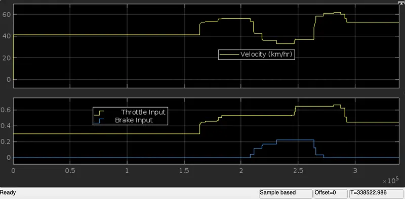
We can see the above result, the variation in vehicle velocity can be observed which change in throttle and brake inputs. When we increasing brake value the speed of velocity is decreses and when we increasing the trottle value the vehicle of velocity increases. by using lookup table it works as close loop by recording the velocity value.
CVT Shaft Speed-
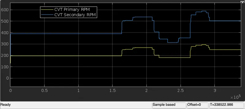
In the above result, the graph indicates the variation in rpm of primary and secondary shafts with respect to input parameter. The Primary shaft increases by increasing throttle value and increases the brake value the primary shaft decreasing and similar to the secondary shaft. The trottle value and brake value can be varying in dashboard , so we can get any particular value for input.
CVT Ratio-
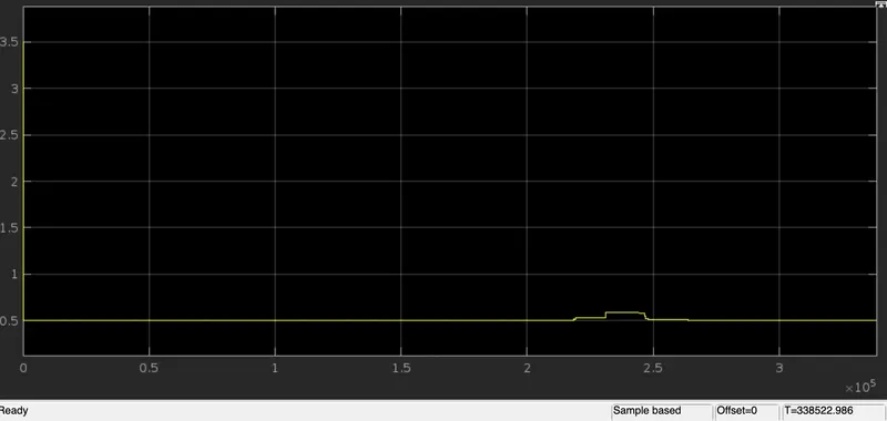
CONCLUSION:
- As the throttle increases the velocity also incrases which intern the power in the engine also increases.
- Velocity , CVT shaft speed and Engine speed are directly proportional to the throttle input and inversly proportional to the brake input.
- CVT ratio is directly proportional to the torque and invertionaly proportional to the trottle input.
- CVT Secondary speed is greater than CVT Primary speed as they are directy proportional to their shaft diameter.
The Given BAJA ATV model was simulated successfully.
REFERENCES:
BAJA ATV Model file.