Week -2
1.Make a Simulink model of Doorbell using solenoid block with the following details:
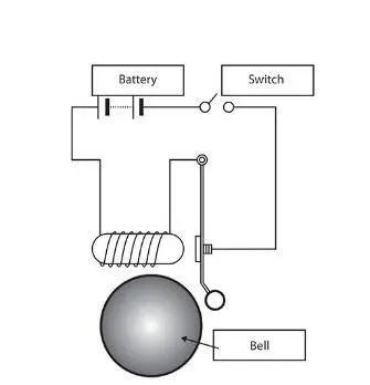
In the above arrangement, when the switch is closed the electromagnet receives electrical power from the battery and pulls the
metal arm to hit the bell producing sound.
Create a situation where the switch is closed for 2 seconds and then released. Observe the physical movement of the
plunger. Assume remaining parameters.
Simulink Model:
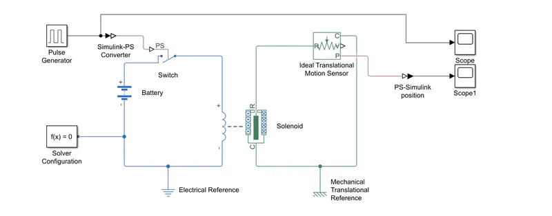
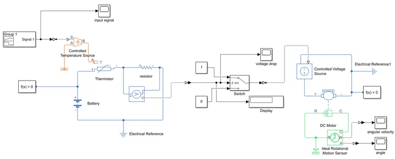
The model consists of the following blocks:
- Pulse generator: Gives input signal to the switch
- Battery: To supply current to solenoid
- Simulink-PS Converter: Converts Simulink signal to physical signal for the switch.
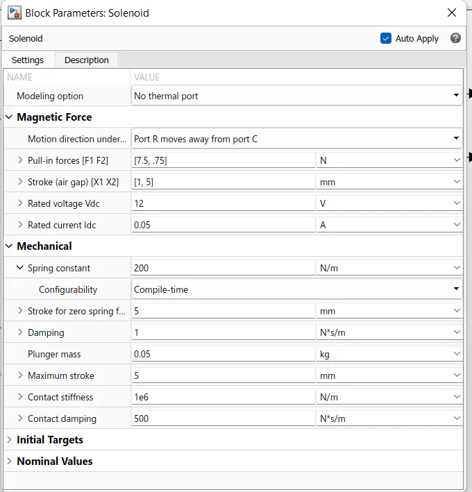
- Solenoid: Works on electromagnetic principle, plunger move towards port R during activation of solenoid the Voltage input for the solenoid is same as the Battery, therefore 12 V input is given.
- Ideal translational motion sensor: Measures the position of plunger with respect to mechanical reference.
- Solver configuration: defines solver settings to use for simulation.
- Electrical reference: Ground for electrical circuit.
- Scope: To plot the graph
- PS-Simulink converter: Converts the signal from physical system to Simulink.
Working:
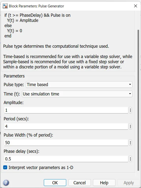
A Pulse Signal Generator is used to turn the switch ON/OFF.
When the circuit is closed, the plunger moves towards port R .
Translational sensor is used to find the Plunger Position.
Input Signal:

Solenoid Properties:
Plunger Position:
Result:
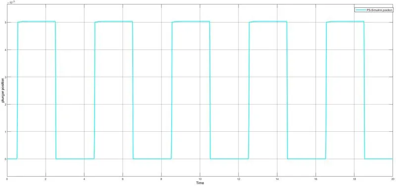
From the graph it can be seen that solenoid's spring is pulling the plunger back to its initial position when the the input signal is 0 and reaches 5mm when the Input signal is 1.
Due to the movement of plunger the metal arm will hit the bell and create the sound.
2.
Aim:To use a thermistor to sense the temperature of a heater & turn on or turn off the fan as per below conditions:
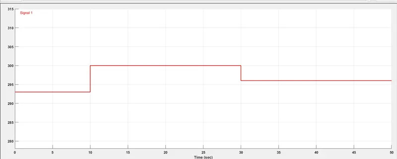
Temperature source: 20 °C from 0 to 10 seconds, 27 °C from 10 to 30 seconds, 23 °C from 30 to 50 seconds
Fan conditions: ON if the temperature above 25 °C, OFF otherwise
Thermistor: A thermally sensitive resistor which changes its resistance w.r.t change in temperature
Two types of thermistor:
NTC (Negative Temperature Coefficient ) thermistor: Resistance decreases with increase in temperature.
PTC (Positive Temperature Coefficient ) thermistor: Resistance increases with increase in temperature.
Simulink Model
Input Signal:
WORKING:
The blocks are connected as shown in the model figure.
Battery, thermistor, resistor, are connected in series to form an electrical circuit.
Signal builder gives the signal to controlled temperature source which is connected to thermistor.
Voltage drop across the resistor is measured and it is given as input to case switch.
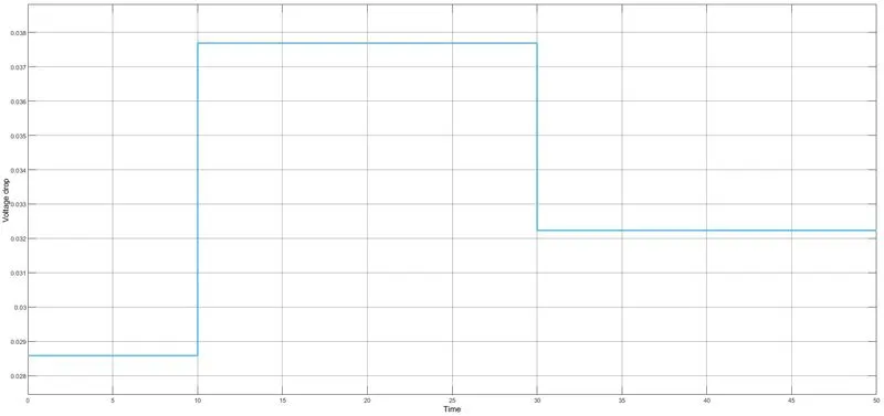
The Threshold is set to 0.03224 V in the case switch, because for 25 degree C the voltage drop across the resistor is 0.03224 V. Whenever the input voltage drop crosses this threshold the switch is closed. When the switch closes, a Controlled Voltage Source drives the DC Motor.
The Motor is connected to an Ideal Rotational Motion Sensor to measure the angular velocity and angle.
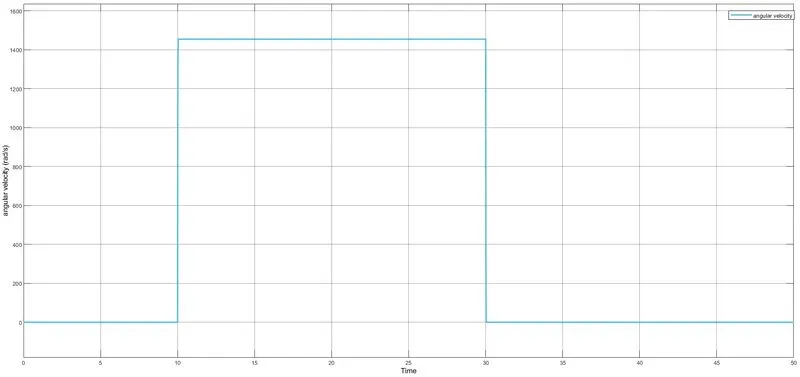
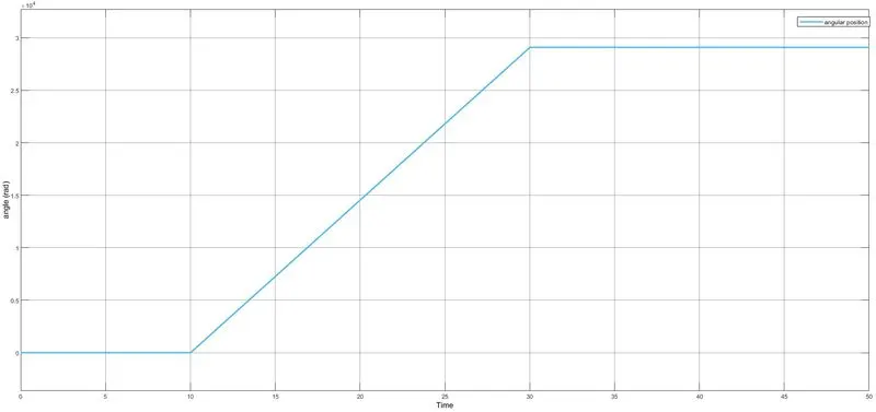
Above is the result of the angular velocity and angle of the motor as a function of time, confirming that the motor is switched on when the temperature is above threshold.
Result:
From the above graphs we can infer that motor(fan) rotates when the temperature is equal or greater than 25 degree C.