Simulink Model Based design of Door bell using Solenoid coil and Automatic Temperature controlled system Using Thermistor
Model-1
Aim: To make a Simulink model of a doorbell using solenoid block
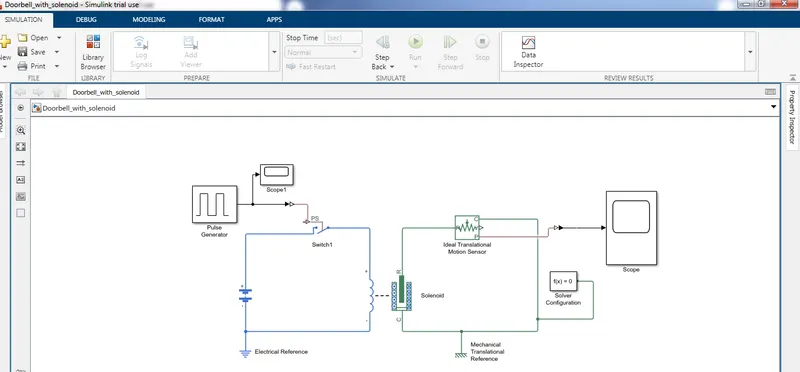
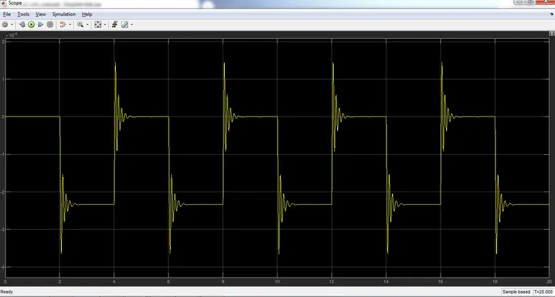
Pulse generator : Pulse generator is used to create square wave pulse at regular intervals, the block waveform parameters amplitude, pulse width, period and phase delay, by this we determined the shape of output waveform Pulse generator parameter need to change for this doorbell model as follows
Amplitude=1
Period=4Secs
Pulse width=50%
Phase delay=2secs
Switch block: The switch block is used to controlled by external physical signal if the external signal is greater than the threshold parameter then the switch is closed otherwise the switch will be remains open
Battery source: The battery source positive terminal is connected to switch and negative terminal of the battery source is connected to solenoid coil positive terminal, electrical reference block need to connect in between
Solenoid coil: Solenoid coil is connected between switch and battery source, this connection is to energize the solenoid and by this electromagnetic action the plunger movement will happens with respect to pulse generator input, Mechanical reference was connected with this mechanical part
Ideal transitional motion sensor : The ideal motion sensor is connected in series with solenoid port moving part R with motion sensor port R and another solenoid coil fixed port C was connected to motion sensor C port, this motion sensor was connected to observe the movement of the plunger
PS-Simulink converter is used to convert the physical signal to Simulink signal
Solver configuration is used in each physical network represented by a connected Simscape blocks, simscape blocks requires the solver setting configuration to perform the simulation
==================================================================
==================================================================
Model-2
Aim: To use a thermistor to sense the temperature of heater and turn off the fan if the temperature is got reduced below 25 Degree Celsius ---> 298 Kelvin
Temperature source:
- 20 Celsius --->293 kelvin from 0 to 10 seconds
- 27 Celsius---> 300 Kelvin from 10 to 30 Seconds
- 23 Celsius ---> 296 Kelvin from 30 to 50 seconds
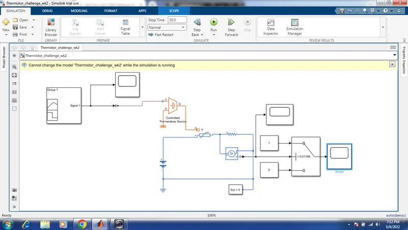
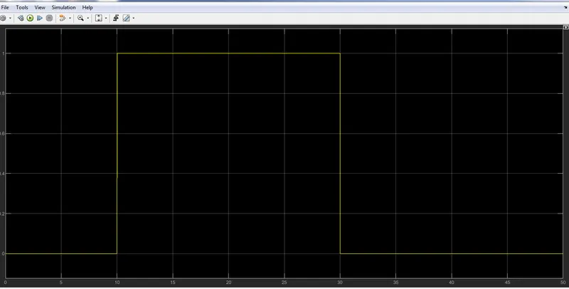
The model was designed with below blocks
Signal Builder: The signal builder is the input derivative for this model, we need to convert the given themperature unit celsius to Kelvin for that we need to add 273 kelvin with this given temperature. By giving a proper input through the signal builder we can get proper result
Controlled temperature Source: The Controlled Temperature Source block represents an ideal source of thermal energy that is powerful enough to maintain specified temperature difference across the source regardless of the heat flow consumed by the system.
Thermistor: Thermistor is a semi conductor that has a resistance capacity more than a conducting material and less than a insulating material. which we used here is a negative temperature co-efficient (NTC) this thermistor will decrease its resistance value when the temperature got increases.
Switch Block: The Switch block passes through the first input or the third input signal based on the value of the second input. The first and third inputs are data input. The second input is a control input. Specify the condition under which the block passes the first input by using the Criteria for passing first input and Threshold parameters.