ADAS Feature project to Determine the direction Vehicle
Vehicle Direction Determination :
Aim of the Project:
- Develop a Simulink model (ADAS Feature) for given requirement Vehicle direction determination as
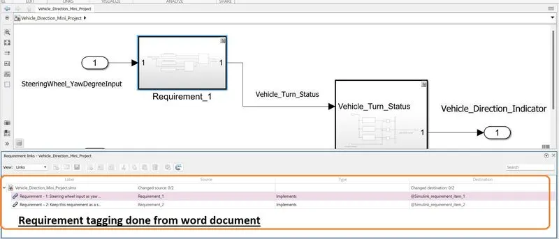
- Tag the requirements to the simulink model; tagging requirement 1 & requirement 2 to their corresponding subsystems.
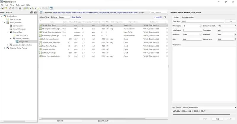
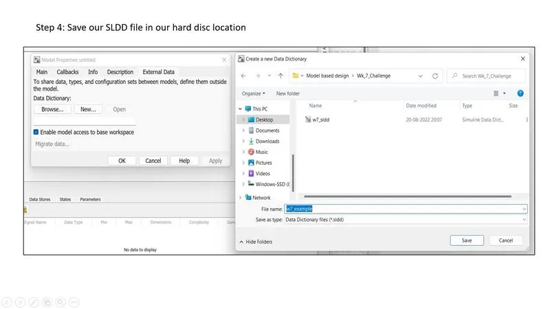
- Create a Simulink Data Dictionary(SLDD) and link with created Simulink model and also generate C code for the created Simulink model would be better
- While choosing the code generation, Need to Storage class for Input signals: ImportedExtern; Storage class for Output signal: Export to File; Storage class for local signals: localizable; Storage class for calibration signals: Const.
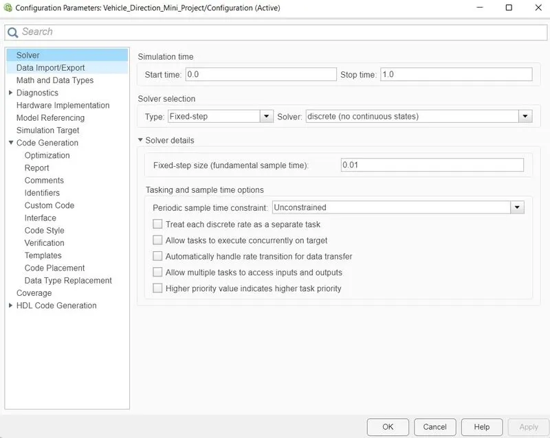
- Choose the solver setting as sample time for all signals as 0.01s
Solution :
As per the given Requirement - 1:
- Steering wheel input as yaw rate (Signal name: SteeringWheel_YawDegreeInput) is the input for this system.
- This is compared against 3 angular values, one each for left turn, right turn & straight drive (Calibration Values: Right_Turn_AngularLimit, Left_Turn_AngularLimit, Straight_Drive_Steering_Angle) to say which specific direction the steering wheel is turning towards.
- Use switch blocks to compare & develop this requirement. Keep this requirement in a subsystem & output of this requirement is a local signal (Signal Name: Vehicle_Turn_Status).
REQUIREMENT MODEL-1 :
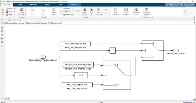
Description of Requirement-1 :
- Steering wheel Rotation (SteeringWheel_YawDegree) is the input to the system and it will be compared using switch blocks with the 3 angular values i.e.(Calibration Values: Right_Turn_AngularLimit, Left_Turn_AngularLimit, Straight_Drive_Steering_Angle) and the output of requirement-1 will be called as local signal (Vehicle_Turn_Status)
- We have SteeringWheel_YawDegreeInput as the Input with 3 constant blocks and 2 switch blocks in this Subsystem. The parameter of constant blocks are feed by us from the Data list given to us
- If the Input is equal or above 30 Right_Turn_Angular Limit will be passed on by 'Switch'. If the Input lies between -120 to 30, 'Switch1' and 'Switch' will pass Straight_Drive_Steering_Angle as the Output. If the Input is lesser than -120, Left_Turn_AngularLimit will be passed on.
- The output of this Subsystem will be Vehicle_Turn_Status.
As per the Requirement – 2:
- Keep this requirement as a separate subsystem. Inputs to this requirement are local signal from requirement 1 (Signal Name: Vehicle_Turn_Status) & an input signal from camera (Signal Name: CameraInput_RoadSign), which confirms the occurrence of a road sign.
- Signal Vehicle_Turn_Status is compared against calibration values (Calibration Values: RightTurn_RoadSign, LeftTurn_RoadSign, Straight_RoadSign), if each of them is found equal, then each of the three corresponding output is compared against the camera input signal,
- Using a logical operator block, only one among them is finally given as output signal (Signal Name: Vehicle_Direction_Indicator).
REQUIREMENT - 2 MODEL DESIGN :
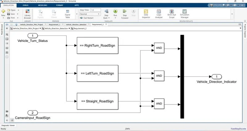
Description of Requirement Model-2 :
- We have two inputs signals in Subsystem_2 , i.e.(Vehicle_Turn_Status and CameraInput_RoadSign).
- (a)The output of Subsystem_1(Vehicle_Turn_Status) will be the Input to Subsystem_2
- (b) another one is input from Camera input (CameraInput_RoadSign)
- Vehicle_Turn_Status input is compared to Roadsign calibration constants, such as Vehicle_Turn_Status will be compared using compare to constant block
- CameraInput_RoadSign if each of them is found equal, then each of the three corresponding output is compared against the camera input signal,Using a logical operator block here we can compare both Vehicle_Turn_Status and CameraInput_RoadSign if both output are high Using Mux block we took only one among them is finally given as output signal (Signal Name: Vehicle_Direction_Indicator)
- MUX took all 3 input signal and helps us to determine one final direction.
Construction_of_Vehicle_direction_detection_Model_Design :
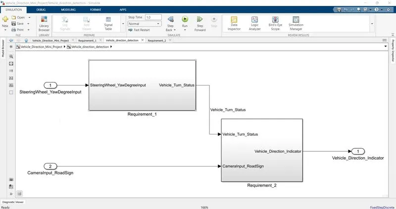
Vehicle_direction_detection_Subsystem :
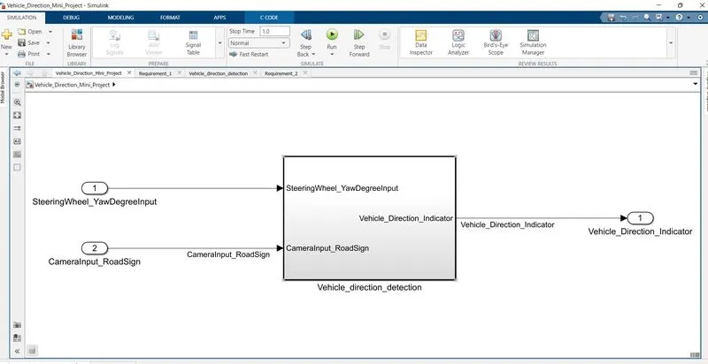
Requirements were linked to subsystem 1 and subsystem 2:
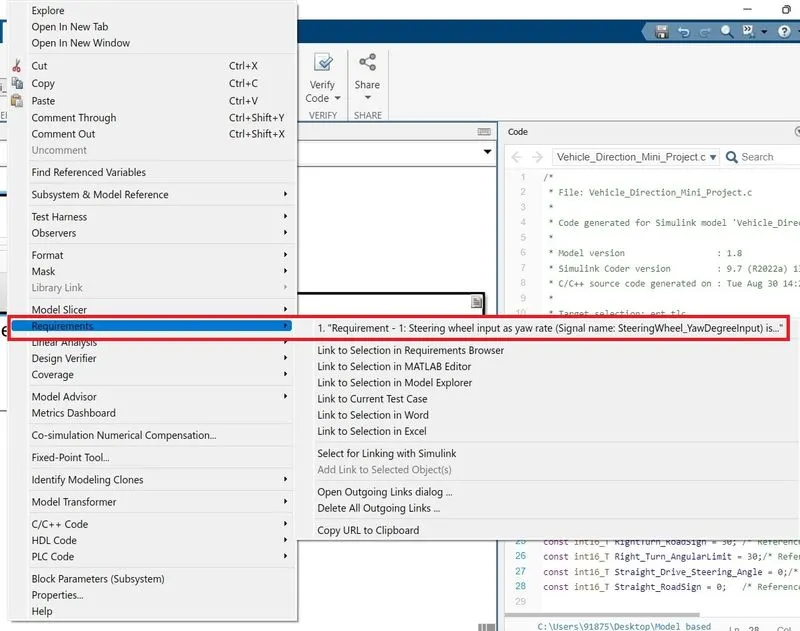
- Requirement Tagging is also one of the Objective of the project. We can do the Requirement Tagging by simply selecting the heading of our requirement in the Word File and then Link the Selection in Word from Requirement section of subsystem.
- After clicking on the Requirement tagged, the Requirement document opens up and the Subsystem is highlighted.
Screenshot-1 :
Sceenshot-2 :
Given Parameters Signals & Calibration Data List:
|
Signal / Calibration Name |
Signal Type |
Data Type |
Dimension |
Min |
Max |
Initial Value |
Units |
|
SteeringWheel_YawDegreeInput |
Input |
Int16 |
1 |
-180 |
180 |
- |
Deg |
|
CameraInput_RoadSign |
Input |
Boolean |
1 |
0 |
1 |
- |
- |
|
Vehicle_Turn_Status |
Local |
Int16 |
1 |
-180 |
180 |
- |
Deg |
|
Right_Turn_AngularLimit |
Calibration |
Int16 |
[1 1] |
-180 |
180 |
30 |
Deg |
|
Left_Turn_AngularLimit |
Calibration |
Int16 |
[1 1] |
-180 |
180 |
-120 |
Deg |
|
Straight_Drive_Steering_Angle |
Calibration |
Int16 |
[1 1] |
-180 |
180 |
0 |
Deg |
|
RightTurn_RoadSign |
Calibration |
Int16 |
[1 1] |
-180 |
180 |
30 |
|
|
LeftTurn_RoadSign |
Calibration |
Int16 |
[1 1] |
-180 |
180 |
-120 |
|
|
Straight_RoadSign |
Calibration |
Int16 |
[1 1] |
-180 |
180 |
0 |
|
|
Vehicle_Direction_Indicator |
Output |
Boolean |
1 |
0 |
1 |
- |
- |
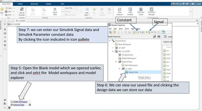
Simulink data dictionary from given Signal and calibration values:
SLDD Creation:
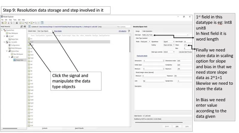
Resolution setting:
Solver settings done per the requirements : Sample time for all signals as 0.01s was chosen
Model Advisor :
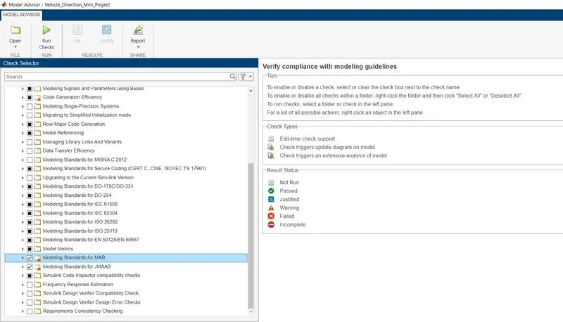
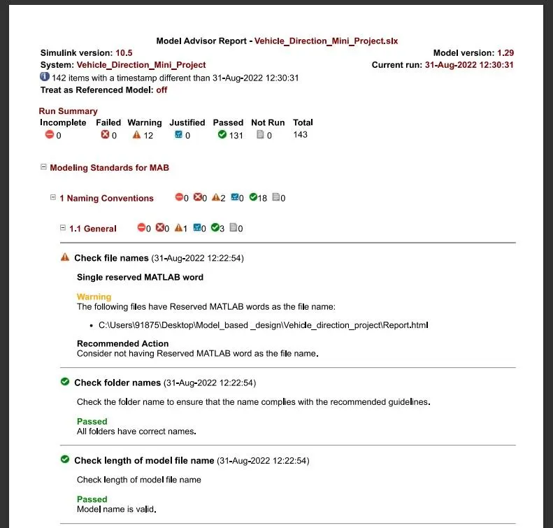
Model advisor as a tool is available in in core Simulink blockset that automatically enables the user to check for common modelling mistakes which we missed out to notice during model development
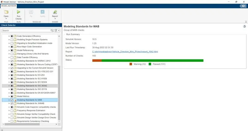
The Model Advisor can analyze the model throughly or a sub set of model upon selecting model advisor option as below, developer can choose which version we would like to test.
Model Advisory Report :
Modelling standards for MAB :
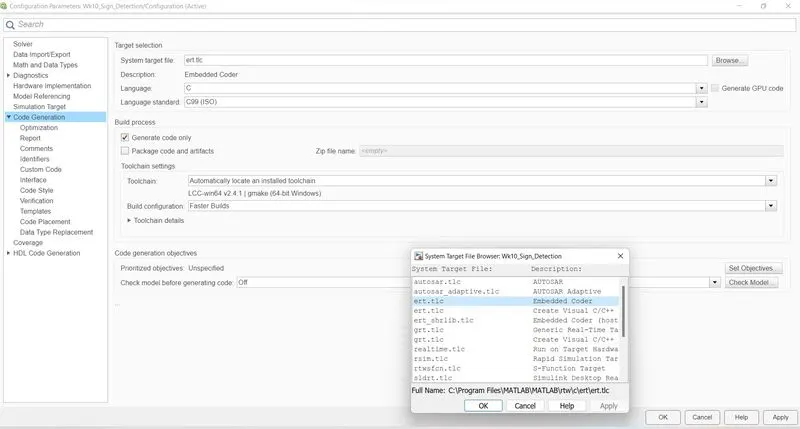
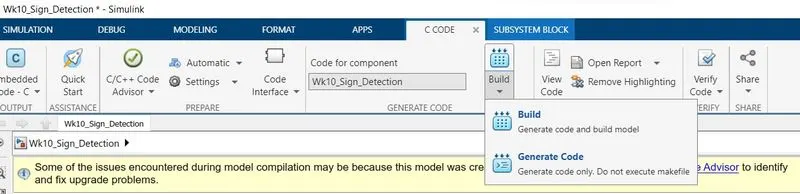
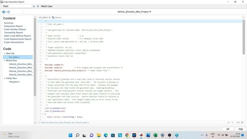
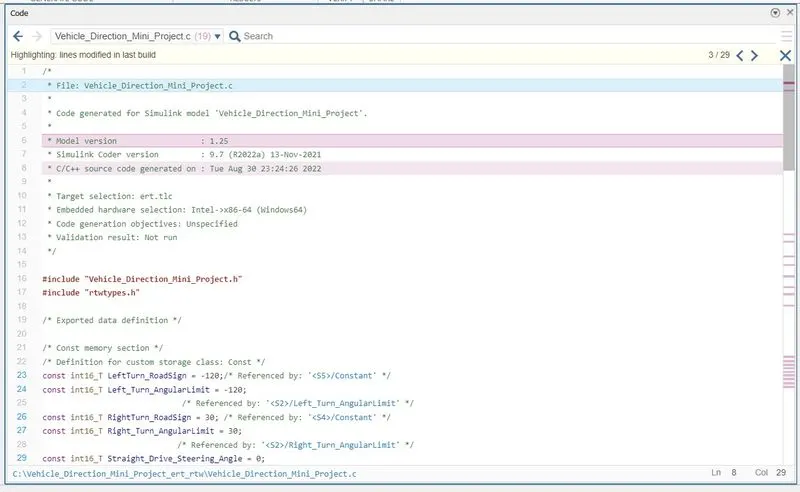
C Code Generation : Code Generation process will be executed by following steps. We have already done the settings required in the Configuration Settings shown below. Now, we simply have to go to Apps section and click on Embedded Coder. Further, we click on Generate Code and we can a window pop-up with our Code. Simulink will create .c and .h files in our model folder, which means our code is successfully generated.
Code Generation Report:
Step by step proccess followed to Accomplish this project :
Step 1 : Read the requirement and Develop the model as per project Requirement, continued to that Project Requirement word document was tagged to the subsystem for better traceability
Step 2 : Read the Given Signal and Calibration data list and then Simulink data dictionary (SLDD) was created properly also File saved
Step 3 : Using the model advisor MAB Guidelines were checked for developed Model. MAB report was taken screenshots were attached
Step 4 : Solver settings and C Code generation settings was done using the Configuration parameters all screenshots were attached
Step 5 : Embedded Code generation done and report was taken file then was attached.
Result : To Verify the Vehicle_direction_determination, I have done the MIL testing by following procedures
1.Test Harness created as per procedures.
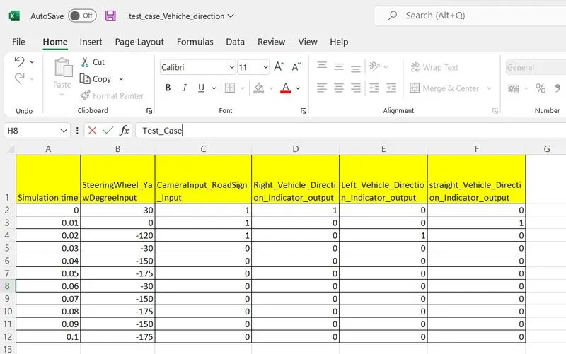
2.Test case was created In Excel file and that test case file was given as input to signal builder
3. Developed Model was verified with the Test case was verified by the model
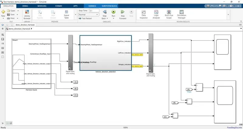
Test_Case: Feeding input to the Signal builder
Verified _Vehicle_direction_determination_Scope_output :
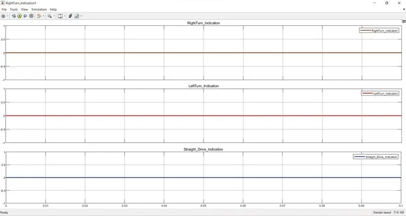
The Vehicle direction determination project was understand and executed properly with above procedures, For reference following files were attached (slx. sldd. Model advisor Pdf file, Requirement.Doc, .C code)