Week -2
Aim:
1. To make a simulink model for door bell using solenoid Block.
2. Use a thermistor to sense the temperature of a heater & turn on or turn off the fan for given conditions
Objective:
Study 1. Create the situation of the Door bell using solenoid Block and switch is closed for 2seconds and Released and the plunger's pysical movement isto observe.
Study 2. Create the situation where the Thermistor is used sense the Temperature of a Heater turn on or turn off the fan and the Temperature is 20 deg celsius from 0 to 10 seconda,27 deg celsius from 10 to 30 seconds,23 deg celsius from 30 to 50 seconds and fan condition is to on for above 25 deg celsius Below means it should be OFF..
Study 1:
Theory:
1. DoorBell:
In the Door Bell usage the most commonly used is the interruptwe it is the type of the mechanical Action it may creates the sound continous where the current is connected into it.
Parts are in the Door Bell connections
1. The Bell
2. Loaded Arm
3. Solenoid
4. Switch
5. Battery
6. Electric contact
process of DoorBell:
The Bell is in the shape of half sphere. The loaded arm is placed in the shoutest distance of the Bell and there is a metal Ball at the end of loaded arm it's only strikes the Bell to create the sound. The loaded Arm is connected to the solenoid only actuating the arm. When the key is open (No currrent is give) the loaded arm doesnot touch the Bell, when the key closed it may repeatelly touching and relasing the Bell so the Ball strikes the Bell creates the sound. when it continous leada to Door Bell sound, The Battery is used for the currents it is due to the magnetic field created by the solenoid which having many windings.
2. Solenoid:
1. The solenoid is an electrical device contains the number of coils to form the electro magnet. The Definition of a solenoid is coil of wire that acts like a magner when a flow of Electricity Passes through it.
2. This solenoid is having the moveable plunger and the number of helical coil spring when the Electric current is given to the coil that is key is closed the Electromagnetic field for arrpimd it.
3. The solenoid mainly converts the electrical Energy into mechanical work and the coil which draws the plunger that's how it works.
BLOCK DIAGRAM:
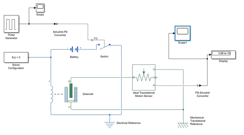
Blocks used:
The Blocks are used in the model of Door Bell.
a) Pulse Generator
b) Simulink-ps convertor
c) switch
d) Battery
e) Solenoid
f) Solver configuration
g) Ideal Translation motion sensor
h) Scope
a) Pulse Generator:
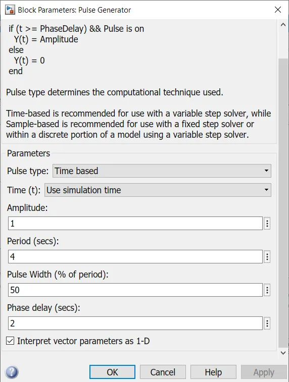
It Generator the square wave form pulses at their intervals. The parameters are Amplitude, Pulsewidth, Period, Phase delay, To determine the wave form.
b) Simulink-ps convertor:
It is the Block used to convert the input simulink signal into the physical connection signals.
c) Switch:
In this Block it is commonly operated by a parameter called Theresold parameter if the signal value greates than the thresold value the switch remains closed otherwise open.
d) Battery:
The Block is used for Deliver the current there is commonly Rechargable Battery.
e) Solenoid:
The solenoid Block is used Producing the mechanical fkorce to move the arm.
f) Solver configuration:
It is required Block for all somscape Block Diagram. It is kind if solver it is necessary to Begin the simulation.
g) Ideal Translation motion sensor:
This Block is used converts the mechanical Translation nodes into control signal proportional to velocity or position.
h) Scope:
The scope is used for generating and showing the result graph with respect to time.
Procedure:
1. The pulse Generator Block is introduced and the inputs parameter are setted which are Amplitude, Pulse width period and phase delay for getting the shape. The scope is connected into it to verify the graph.
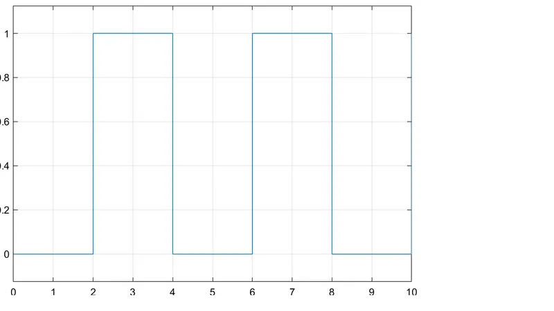
2. Followed By the pulse Generator simulink-ps convertor is used and sends to switch Block.
3. The Battery is connected to the end of the switch and it is ground by using the electrical Reference and the solver configuration also connected.
4. The solenoid Block is connected to circuit the positive terminal connect to switch and negative is grounded.
5. The C is connected to the mechanocal Teanslational Refremce and R is connected to Ideal Translation motion sensor R and the Another mechanical Translational is connected and corresponding scope is connected for Graph display.
Results and Discussion:
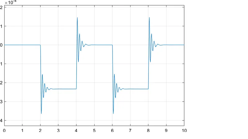 This Above diagram shows the Result output of the given objective, and clearly abserves that the wave forms for the fist 2 seconds and it Breaks for another 2 seconds and then it continous, and the plunger remains oscllates for half a second because of Damping effect.
Conclusion:
We can conclude that the given Aim is analyzed and the Block diagram is made and simulation is done.
-------------------------------------------------------------------------------------------------------------------------
Study 2:
Thermistor:
A Thermistor is a type of resistor whose Resistance is strongly dependent on temperature the Resistance varies with changes in Temperature. The Temperature will fluctuate slightly Because it is sensitive to Temperature Changes.
There are two types of Thermistors:
a) Negative Temperature coefficient Thermistor.
b) Positive Temperature coefficient Thermistor.
a) Negative Temperature coefficient Thermistor(NTC)
In the NTC Thermistor, The Process is defined as the Temperature increasesand the Resistance Decreases and it also converses that It the TEmperature decreases and the Resistance increases, so in the NTC thermistor the Temperature and Resistance are conversely proportional.
b) Positive Temperature coefficient Thermistor(PTC)
In the PTC Thermistor. the process is defined as the When an Temperature increases and also when the Temperature decreases, Resistance Decreases so it is Known as the inversely proportional.
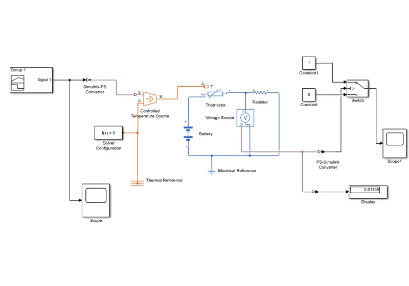
BLOCK DIAGRAM:
Block used:
Signal Builder:
This Signal Builder Block is used for create the interchangeable groups of Piecewise linear signl sources for rsing this we can Rapidly change the signal Groups.
Simulink-ps converter:
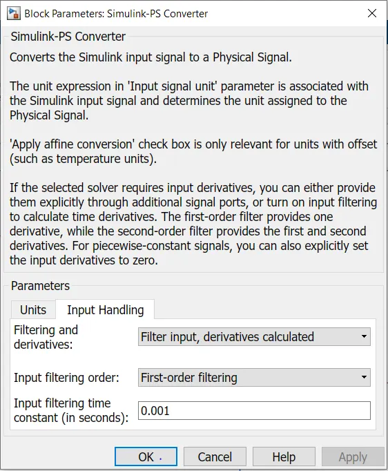
The simulink-ps converter Block converts the simulink signal into to physical signal.
controlled Temperature source:
This controlled Temperature source Block is used for representing the ideal source of Thermal energy it is for keep the specified Temperature difference across the heat flow consumed by the system.
Thermal Reference:
It Represents a Thermal Reference point, it is the point wdith an absolute zero Temperature with Respect to Temperature.
Thermistor:
The thermistor Block Respresents an NTC Thermistor, the Thermistors are Normally used for secsing the Temperature.
voltage sensor:
The voltage sensor is normally used for sensing the volage measured Between Two points of an circuit
Display:
the Display Block is Generally used for showing the output value, the output is performed Based on the inputs and Blocks
Explanation and Procedure:
1. The simulation process is starts with connecting the Blocks so first the Themistor(NTC) Block is connected, and then T port is connect into the controlled Temperature source in that source the signal Builder is cinnected with the use of the simulink-ps convertor and then the Thermal Reference.
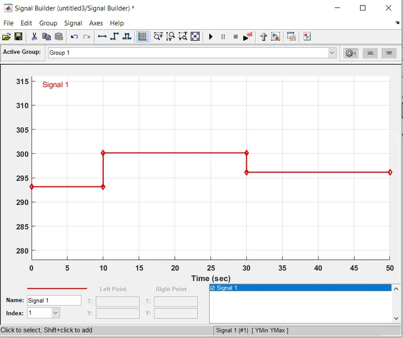
2. In the signal builder the input signal that will be created Based on the question asked.
0-10 sec - Temperature is 293.15k(20 deg celsius)
10-30 sec - Temperature is 300.15k(27 deg celsius)
30-50 sec - Temperature is 296.15k(23 deg celsius)
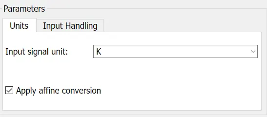
All the Temperature are converted to kelvin, Because of the unavailable option in deg- celsius.
3. The solver configuration is connected on the connection of Thermistor and voltage sensor for the positive terminal side on thr negative terminal is connected to Battery and Ground the Battery is connected to Thermistor and voltage sensor.
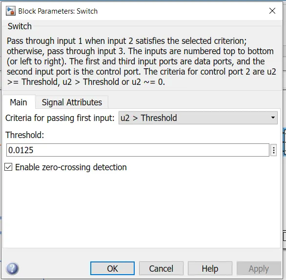
4. There is a V connection in the voltage sensor connected to switch with the use of ps- simulink convertor, the scope is used in between convetor to switch and the two switch and the another scope is connected there of ps-simulink convertor.
Results and discussion:
After the All connection are made the simulation will be run for 50 sec.
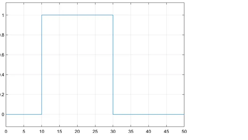
This Above Graph shows that for ot losec the signal is 0 Because the Temperature 20 deg celsius so, the fan switch kept OFf and another set 10 to 30 sec the signal is 1 because the Temperature 27 deg celsius so the fan switch kept ON, and for 30 to 50 sec the signal 0 Becauses the Temperature is 23 deg celius so the fan kept OFF.
It is clearly shows when the Temperature greater 25 deg celsius the signal will be one and fan switch ON.
Conclusion:
We can conclude that the given Aim is analyzed and the Block diagram is made and simulation is done.