Week -2
Aim
- Make a Simulink model of Doorbell using solenoid block with the following details:
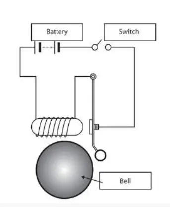
Objective- when the switch is closed the electromagnet receives electrical power from the battery and pulls the metal arm to hit the bell producing sound.
Create a situation where the switch is closed for 2 seconds and then released. Observe the physical movement of the plunger.
2. Use a thermistor to sense the temperature of a heater & turn on or turn off the fan as per the below conditions:
Temperature source: 20 °C from 0 to 10 seconds, 27 °C from 10 to 30 seconds, 23 °C from 30 to 50 seconds
Fan conditions: ON if the temperature above 25 °C, OFF otherwise.
Theory
- Making a Simulink model of Doorbell using solenoid block
Sometimes the simplest things are the ones that people are most unaware of. Take the case of a door bell. How many people have ever taken a moment out of their busy schedule to think about a door bell works. How often do we use this electrical machine in a day? Several times a day most likely. This simple machine is actually fascinating in the way it uses a basic principle of electromagnetism to work in an innovative way. Science of simplicity at its best!
Working Principle
The most important part of a door bell is its magnetic motor. The magnetic motor constitutes a conventional electromagnet. We know that an electromagnet is an arrangement in which a coil of wire is wrapped around magnetic material which produces magnetic field when electricity is passed through the coil. The greater the coiling of the wire, the higher the amplification of magnetic field. This magnetic field produces a substantial effect on any magnetic substance when brought in the vicinity of its magnetic field. This means that when an iron object is placed in this magnetic field, it will be attracted towards the magnetic field due to polar orientation generated by the electromagnetism.
Process
When the door bell button is pressed, an electrical circuit is closed, which leads to the flowing of electric current through the electromagnet.
This current passes through a transformer which turns the 120 V current into usable 10 V current. The current then passes through the electromagnetic wire winding. A magnetic field is generated as a result, which is used to drive a sound making mechanism. Different types of sound making mechanisms are used to generate different sorts of noises.
The three main types of sound making mechanisms are as follows.
Buzzer
The simplest kind of door bell mechanism, a buzzer, works with the help of an electromagnet whose two ends of the winding are connected to the electrical circuit. One end of the winding is connected directly to the electrical circuit while the other end of the wire is connected to a metal contact placed adjacent to a moving contact arm. The contact arm is a light thin metal arm, whose one end rests against the contact point, while the other end is anchored and connected to the electrical circuit.
When the door bell button is pressed, the electrical circuits closes and results in the generation of an electromagnetic field. The magnetic field attracts the iron bar, which pulls the contact arm away from the metal contact. The moving away of the contact arm breaks the circuit and thus turns off the electromagnet. The contact arm snaps back to its original position. This closes the electrical circuit and reestablishes the flow of electrical current through the circuit. Once again the magnetic field is generated and the process repeats itself.
The sound is generated due to the contact arm hitting rapidly to the magnet and the stationary contact, several times in a second.
Bell
The bell also runs on the same principle with the only difference that the moving arm is connected to a clapper which rests against a circular metal plate. The process takes place in the same way as in Buzzer, with the arm moving back and forth and the clapper hitting the bell repeatedly.
Chime
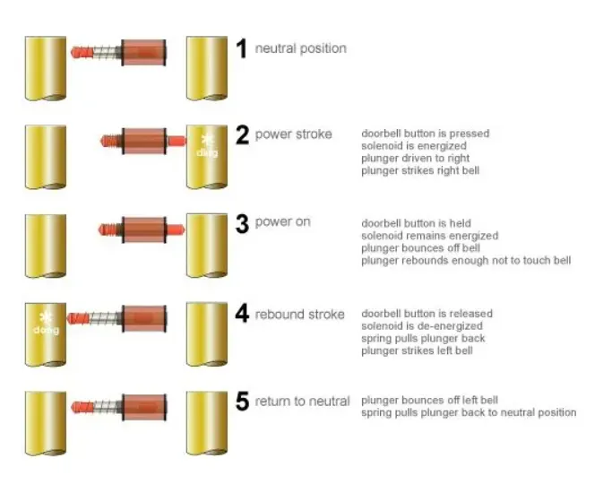
The chime door bell uses a solenoid to generate the noise. Solenoid is an electromagnet with wire winding and a small metal piston inside it. The piston is attached to a spring assembly inside the wire winding. When electric current flows through the wire,electromagnetic field is generated which pulls the metal piston towards it. The metal piston hits the tone bar located on both the sides of the arrangement. When the door bell button is released, the spring snaps the piston back to its original position and the piston hits the tone bar on the other side of the arrangement. The two tone bars are made and arranged in such a way that the hitting action produces a ding-dong sound.
Following Blocks are used here for Door bell model
1). Pulse Generator:
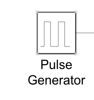
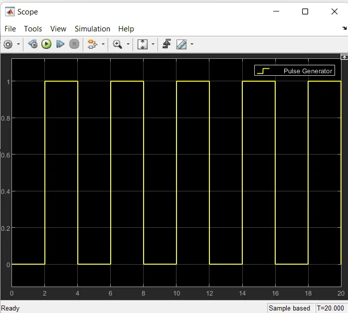
The Pulse Generator block generates square wave pulses at regular intervals. The block waveform parameters, Amplitude, Pulse Width, Period, and Phase delay, determine the shape of the output waveform. The following diagram shows how each parameteraffects the waveform.
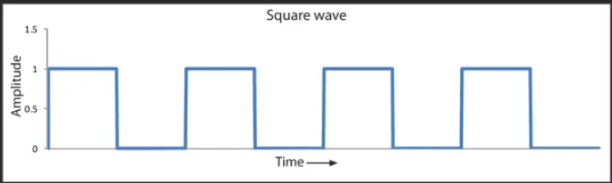
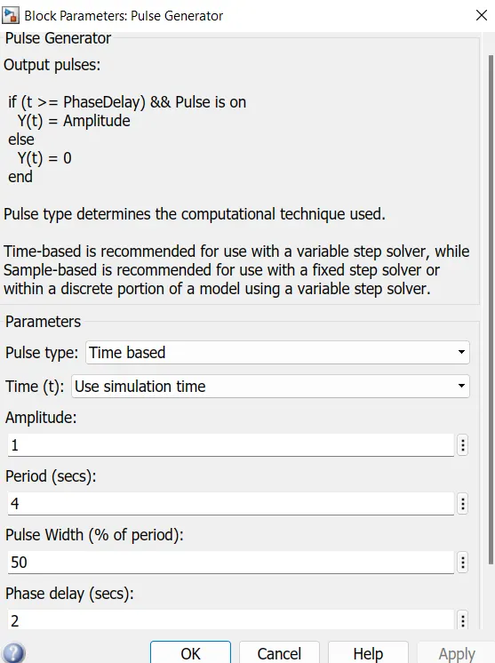
From the above figure we can observe we have given period value as “ 4 ” pulse width as ‘50’, phase delay as ’2’ and Amplitude by default is ‘1’ we have not changed it. This means that initially the Pulse will be Zero, Since we have given Phase Delay of “2” so till 2 sec the Pulse will be Zero and at the end of 2 sec the Pulse will start rising from Zero to 1, Since we have given Amplitude as “1” and then now the Pulse width will be Half of Period, So for the next 2 seconds the Pulse will be at Amplitude “1” only, then it will again come down to zero at 4 Second and then it will be Zero. So, after these 4 seconds period again the pulse will be generated and thus cycle continues.
From starting to ending of the Pulse it will take 4 sec of time period in which only for 2 secs the Amplitude will be “1” and for rest of time it will be Zero. So, after these 4 secs period again the Pulse will be generated and thus Cycle continues.
To this “Pulse Generator” a “Scope Block” is connected to see how the Pulse is generated.
2) Battery
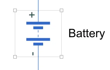
This block models a battery. If you select Infinite for the Battery charge capacity parameter, the block models the battery as a series internal resistance and a constant voltage source. If you select Finite for the Battery charge capacity parameter, the block models the battery as a series internal resistance plus a charge-dependent voltage source defined by:
V = Vnom*SOC/(1-beta*(1-SOC))
where SOC is the state of charge and Vnom is the nominal voltage. Coefficient beta is calculated to satisfy a user-defined data point [AH1,V1].
3)Switch
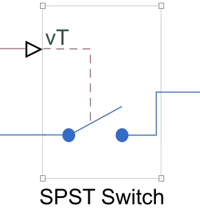
The block represents a Single-Pole Single-Throw (SPST) switch controlled by an external control signal vT. If vT is greater than the threshold, then the switch is closed, otherwise the switch is open.
If a non-zero threshold width is defined, then the switch conductance varies smoothly between off-state and on-state values as vT varies between threshold and threshold plus threshold width. The threshold width must be zero to enable switched linear solver optimizations.
Right-click on the block and select Simscape block choices to access variant implementations of this block.
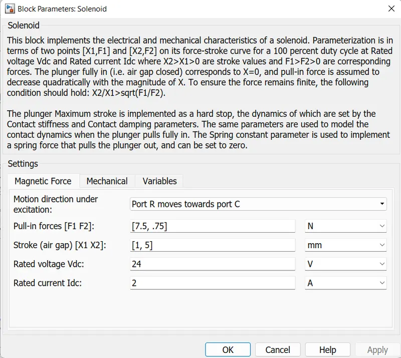
4) Solenoid Block
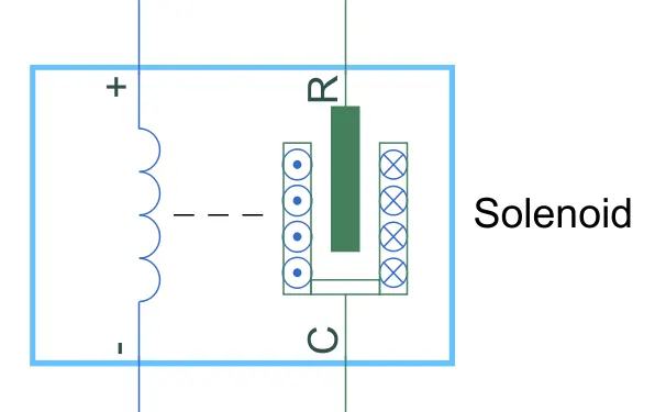
This block implements the electrical and mechanical characteristics of a solenoid. Parameterization is in terms of two points [X1,F1] and [X2,F2] on its force-stroke curve for a 100 percent duty cycle at Rated voltage Vdc and Rated current Idc where X2>X1>0 are stroke values and F1>F2>0 are corresponding forces. The plunger fully in (i.e. air gap closed) corresponds to X=0, and pull-in force is assumed to decrease quadratically with the magnitude of X. To ensure the force remains finite, the following condition should hold: X2/X1>sqrt(F1/F2).
The plunger Maximum stroke is implemented as a hard stop, the dynamics of which are set by the Contact stiffness and Contact damping parameters. The same parameters are used to model the contact dynamics when the plunger pulls fully in. The Spring constant parameter is used to implement a spring force that pulls the plunger out, and can be set to zero.
5)Ideal Translation Motion Sensor Block
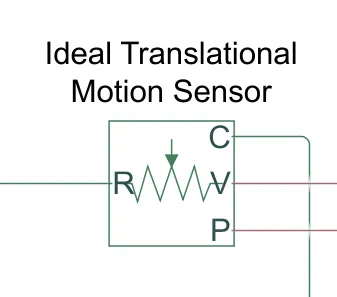
This block measures velocity or displacement in a mechanical translational network. The sensor is ideal since it does not account for inertia, friction, delays, energy consumption, and so on.
The physical signal ports V and P report the velocity and position, respectively, of port R relative to port C. The measured velocity is positive when the velocity at port R is greater than the velocity at port C.
6)Scope
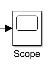
Scope is connected with Ideal Translation Motion Sensor to get the output. The real-time Scope block acquires data in chunks of size Number of samples from the real-time application that is executing on the target computer.
7)PS-Simulink Converter:
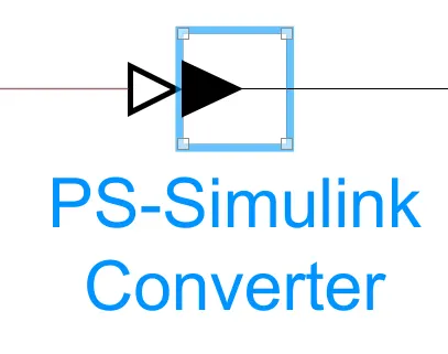
The PS-Simulink Converter block converts a physical signal into a Simulink output signal. Use this block to connect outputs of a Physical Network diagram to Simulink scopes or other Simulink blocks.
8)Simulink-Ps Converter:
This Block convert simulink signals into physical signal for operational use in Model.
9)Electrical Reference Block:
The Electrical Reference block represents an electrical ground. Electrical conserving ports of all the blocks that are directly connected to ground must be connected to an Electrical Reference block. A model with electrical elements must contain at least one Electrical Reference block.
10)Mechanical Translation Reference Block:
The Mechanical Rotational Reference block represents a reference point, or frame, for all mechanical rotational ports. All rotational ports that are rigidly clamped to the frame (ground) must be connected to a Mechanical Rotational Reference block.

11) Solver Configuration:
Each physical network represented by a connected Simscape block diagram requires solver settings information for simulation. The Solver Configuration block specifies the solver parameters that your model needs before you can begin simulation.
Simulink model of Doorbell using solenoid block
EXPLANATION:
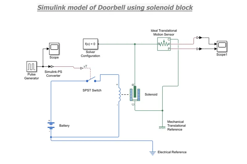
- Above block diagram shows the systematic arrengment of various blocks in such a way that getting required output.
- Now first a “Solenoid block” and “Battery Block”are taken from the library Browser.
- Then this “Solenoid Block” & “Battery Block” are connected to each other via positive and negative terminals.
- A “Switch Block” is placed between “Solenoid Blocks” and “Battery Block “and is connected with both Blocks.
- Now for operate Switch we need to provide Physical signal through “PS” port in the “Switch Block”.
- The provided physical signal should be greater than the threshold of the switch, for switch being close, or else it will be open.
- Now this whole Battery Switch and Solenoid path is connected to an “Electric Reference Block” which represents earthing of the circuit.
- This “Electric Reference Block” should be connected to the negative terminal of “Battery Block”.
- Then in the solenoid block “R” and”C” are two variable which represent Plunger and Fixed Point respectively.
- Now the solenoid “R” is connected to “R” of “Ideal Translation Motion Sensor Block” which senses the position of plunger in the Solenoid Block and gives the Output.
- Now in the “Ideal Translation Motion Sensor Block” the output are given as “V” & ”P” which represent the velocity and position of the plunger.
- Since we are only interested in knowing the change in position of the plunger, so we need only results of “P” output.
- Now “C” in the “Ideal Translation Motion Sensor Block” is a mechanical translation conserving port, which means that the
mechanical process starts from “R” and end at “C” and again it start at “R” and the cycle goes on. - So “C” in the “Ideal translation Motion sensor block” is connected to “Mechanical Translation Reference” which represents a fix point where it is rigidly clamped in real time.
- Similarly “C” of the solenoid block is also connected to the same “Mechanical Translation Reference” as fixed point for solenoid.
- Since we have position of the plunger as output from “Ideal Translation Sensor Block” we have connected port”p” to a ‘PS-Simulink Converter’ where the Physical value from port ’P’ are converted into Simulink value, and then this ‘PS-Simulink Converter’ is connected to ‘Scope Block’ which will generate a graph for change in position of Plunger from port ‘P’ of ‘Ideal Translation Motion Sensor Block’.
- Now to provide a physical signal for operating the switch, we have used a “Pulse Generator Block”, which generates a
continuous Square Pulse. - Now Run the Model and Double click on the “Scope2 Block” which is connected to “Ideal Translation Motion Sensor Block” to getthe results.
- We will get the above Graph as the result when we double click on “Scope2 Block”. Here X-axis Represent the “Time” and the Y axis represent position of Plunger in mm.
RESULTS
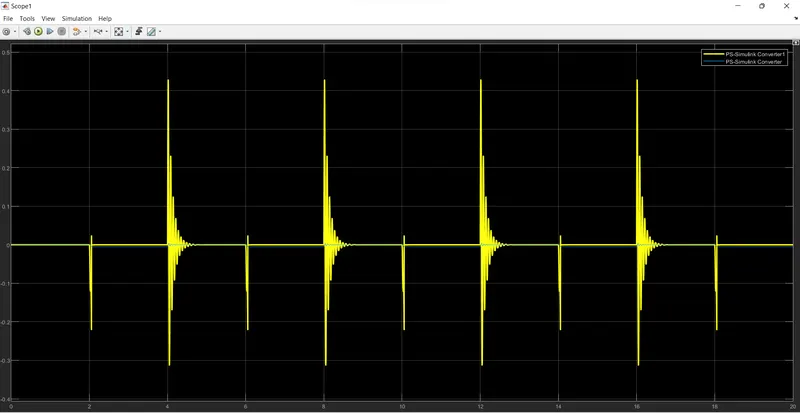
Square Wave generated in Pulse generator
conclusion
1)When the switch is closed the electromagnet receives electrical power from the battery and pulls the metal arm 'R' and to hit the "C" pad.
2)The switch is closed for 2 seconds and then released. Observed the physical movement of the plunger and striker .This movement shown in the graph.
- 2] Use of the thermistor to sense the temperature of a heater & turn on or turn off the fan
Objective
Temperature source: 20 °C from 0 to 10 seconds, 27 °C from 10 to 30 seconds, 23 °C from 30 to 50 seconds
Fan conditions: ON if the temperature above 25 °C, OFF otherwise.
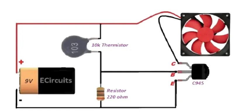
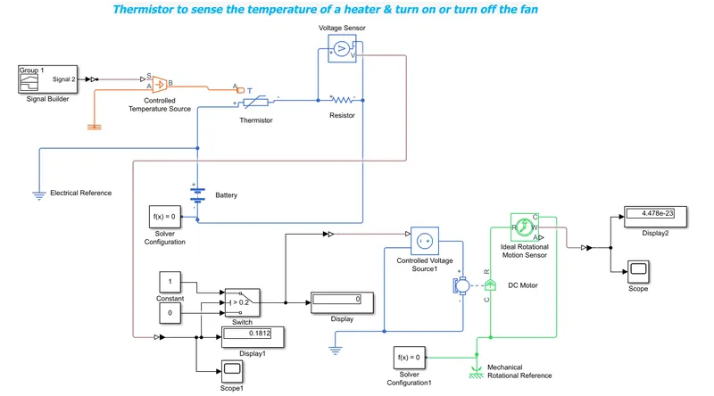
Fig shows the Sketch of Battery,Thermister and Fan model
A thermistor (or thermal resistor) is defined as a type of resistor whose electrical resistance varies with changes in temperature. Although all resistors’ resistance will fluctuate slightly with temperature, a thermistor is particularly sensitive to temperature changes.
Thermistors act as a passive component in a circuit. They are an accurate, cheap, and robust way to measure temperature.While thermistors do not work well in extremely hot or cold temperatures, they are the sensor of choice for many different applications.Thermistors are ideal when a precise temperature reading is required. The circuit symbol for a thermistor is shown below:

Uses of Thermistors
Thermistors have a variety of applications. They are widely used as a way to measure temperature as a thermistor thermometer in many different liquid and ambient air environments. Some of the most common uses of thermistors include:
- Digital thermometers (thermostats)
- Automotive applications (to measure oil and coolant temperatures in cars & trucks)
- Household appliances (like microwaves, fridges, and ovens)
- Circuit protection (i.e. surge protection)
- Rechargeable batteries (ensure the correct battery temperature is maintained)
- To measure the thermal conductivity of electrical materials
- Useful in many basic electronic circuits (e.g. as part of a beginner Arduino starter kit)
- Temperature compensation (i.e. maintain resistance to compensate for effects caused by changes in temperature in another part of the circuit)
- Used in wheatstone bridge circuits
How Does a Thermistor Work
The working principle of a thermistor is that its resistance is dependent on its temperature. We can measure the resistance of a thermistor using an ohmmeter.
If we know the exact relationship between how changes in the temperature will affect the resistance of the thermistor – then by measuring the thermistor’s resistance we can derive its temperature.
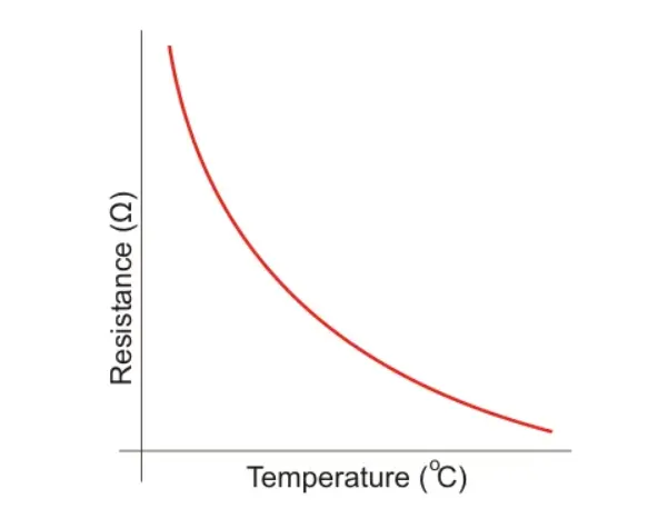
How much the resistance changes depends on the type of material used in the thermistor. The relationship between a thermistor’s temperature and resistance is non-linear. A typical thermistor graph is shown below:
There are two types of thermistors:
- Negative Temperature Coefficient (NTC) Thermistor
- Positive Temperature Coefficient (PTC) Thermistor
NTC Thermistor
In an NTC thermistor, when the temperature increases, resistance decreases. And when temperature decreases, resistance increases. Hence in an NTC thermistor temperature and resistance are inversely proportional. These are the most common type of themistor.
PTC Thermistor
A PTC thermistor has the reverse relationship between temperature and resistance. When temperature increases, the resistance increases.
And when temperature decreases, resistance decreases. Hence in a PTC thermistor temperature and resistance are inversely proportional.
Although PTC thermistors are not as common as NTC thermistors, they are frequently used as a form of circuit protection. Similar to the function of fuses, PTC thermistors can act as current-limiting device.
Thermistor Construction
To make a thermistor, two or more semiconductor powders made of metallic oxides are mixed with a binder to form a slurry.
Small drops of this slurry are formed over the lead wires. For drying purposes, we have to put it into a sintering furnace.
During this process, the slurry will shrink onto the lead wires to make an electrical connection.
This processed metallic oxide is sealed by putting a glass coating on it. This glass coating gives a waterproof property to the thermistors – helping to improve their stability.
There are different shapes and sizes of thermistors available in the market. Smaller thermistors are in the form of beads of diameter from 0.15 millimeters to 1.5 millimeters.
Thermistors may also be in the form of disks and washers made by pressing the thermistor material under high pressure into flat cylindrical shapes with a diameter from 3 millimeters to 25 millimeters.
The typical size of a thermistor is 0.125mm to 1.5 mm. Commercially available thermistors have nominal values of 1K, 2K, 10K, 20K, 100K, etc. This value indicates the resistance value at a temperature of 25oC.
Simulink model
BLOCKS USED & ITS WORKING:
Signal builder: Used to feed a signal on the given condition of temperature.Note that temperature should be in kelvin (since the temperature source and thermistor operates in kelvin)
Controlled temperature source: Based on the signal provided it creates a controlled temperature difference at port B.
Thermal reference: It gives the initial condition to the temperature operated blocks with absolute zero temperature.
Battery: A power supply is provided which may be dc voltage source or a battery to operates the thermistor.
Thermistor: It performs the thermistor operation with the temperature input from the controlled temperature source.
Resistor: The resistor is connected to thermistor where the changes in resistance can be viewed from the voltage sensor block which is connected in parallel circuit.
Voltage Sensor :
The block represents an ideal voltage sensor, that is, a device that converts voltage measured between any electrical connections into a physical signal proportional to the voltage.
Switch: This switch has three ports , the port 2 checks the condition ,if it satisfies the it follows port 1 and orelse it follows port 3 . It's a signal routing switch . The threshold limit for the port 2 check condition is the voltage sensed on temperature input of 25 deg. celcius. The value in the display block is the threshold value.
DC motor: This is used in the place of fan in modelling.The dc motor needs a power supply ,it is feed by the controlled voltage source block.
Ideal rotational motion sensor: The movement of the dc motor is sensed by this block having R and C as input conserving ports ,the angular displacement and the velocity are measured.
Electrical reference block: A model with electrical block must contain this reference port it implies the electrical ground.
Mechanical Rotational reference:It represents frame or ground where the mechanical rotational blocks are mounted.
Solver configuration: The solver configuration model is essential for all simscape models .It sets up the solver setting for simulation.
Scope: It displays the provided input in graphical representation.
Results
1) Time vs Temperature graph in signal builder block
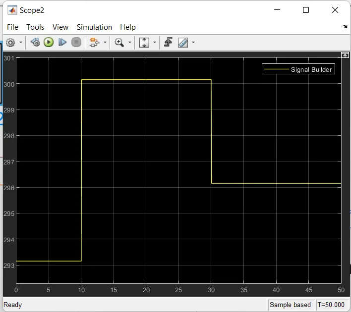
Temperature source: 20 °C from 0 to 10 seconds, 27 °C from 10 to 30 seconds, 23 °C from 30 to 50 seconds.
2) Voltage change in Voltage sensor block
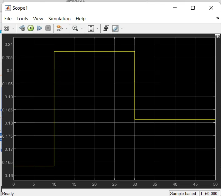
Voltage changes according to time and temperature due to thermistor .
3) Fan On/Off condition
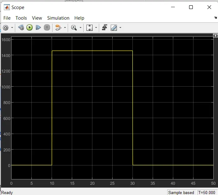
Above graph shows the fan ON/off if the temperature above 25 °C, OFF otherwise.For time 10 sec to 30 sec the temperature senced in model is above 25 degree ffor that temperature the resistance in thermistor decreses and current increases and fan start running . After 30sec fan is off because the temperature is 23 degree and condition is not satisfied in switch block, voltage is below Threshold value so that fan should be off in model.
conclusion
The thermistor controlled fan was modelled and simulated as per the given instruction successfully using the simulink .
References: