Week -2
Aim:
- To make a Simulink model of doorbell using a solenoid block.
- To make a simulink model using a thermistor to sense the temperature of a heater & turn on or turn off the fan for the given conditions:Temperature source: 20 °C from 0 to 10 seconds, 27 °C from 10 to 30 seconds, 23 °C from 30 to 50 secondsFan conditions: ON if the temperature above 25 °C, OFF otherwise.
Objective:
- For the model of doorbell using a solenoid block we have to create a situation where the switch is closed for 2 seconds and then released and observe the position of the plunger.
- For the model where we use a thermistor to sense the temperature of heater we have create a model as per the given conditions:
- Temperature source:
- 20 °C from 0 to 10 seconds.
- 27 °C from 10 seconds to 30 seconds.
- 23 °C from 30 seconds to 50 seconds.
- Temperature source:
2. Fan conditions:
1. ON if the temperature is above 25 °C, OFF otherwise.
Theory:
Solenoid:
A solenoid is a type of electromagnet, the purpose of which is to generate a controlled magnetic field through a coil wound into a tightly packed helix. The coil can be arranged to produce a uniform magnetic field in a volume of space when an electric current is passed through it. In electromagnetic technology, a solenoid is an actuator assembly with a sliding ferromagnetic plunger inside the coil. Without power, the plunger extends for part of its length outside the coil; applying power pulls the plunger into the coil.
The basic components used to setup a simple doorbell circuit are:
- Battery
- Switch
- Solenoid
- A bell with a plunger
Thermistor:
A thermistor is a type of resistor whose resistance is dependent on temperature, more so than in standard resistors. The word is a combination of thermal and resistor. Thermistors are widely used as inrush current limiters, temperature sensors (negative temperature coefficient or NTC type typically), self-resetting overcurrent protectors, and self-regulating heating elements (positive temperature coefficient or PTC type typically).
Thermistors are of two opposite fundamental types:
With NTC thermistors, resistance decreases as temperature rises. An NTC is commonly used as a temperature sensor, or in series with a circuit as an inrush current limiter.
With PTC thermistors, resistance increases as temperature rises. PTC thermistors are commonly installed in series with a circuit, and used to protect against overcurrent conditions, as resettable fuses.
The basic components used to setup a simple cooling fan circuit are:
- Battery
- Thermistor
- Fan
- Resistor
- votmeter
Models:
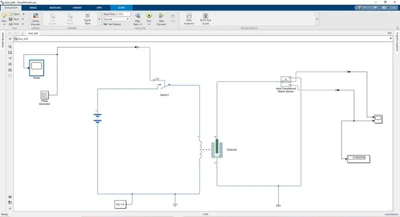
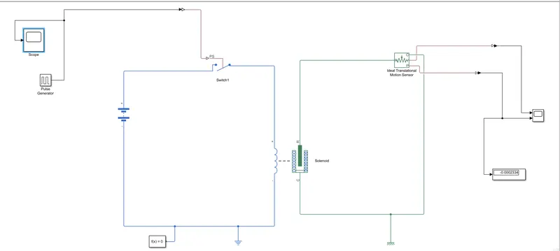
1) simulink Model of door bell arrangement:
Procedure:
BLOCKS USED: -
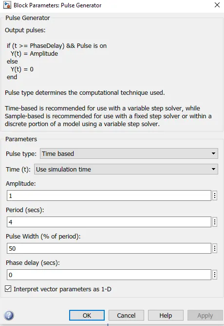
Beat Generator: - The Pulse Generator block creates square wave beats at normal stretches. The square waveform boundaries, Amplitude, Pulse Width, Period, and Phase delay, decide the state of the result waveform.
Simulink-PS Converter: - The Simulink-PS Converter block changes over the info Simulink signal into an actual sign. Utilize this square to associate Simulink sources or other Simulink squares to the contributions of a Simscape actual organization.
Switch: - The Switch block models a switch constrained by an outside actual sign. Assuming the outside actual sign PS is more noteworthy than the worth indicated in the Threshold boundary, then the switch is shut, generally the switch is open.
Battery: - The Battery block executes a conventional unique model that addresses the most well known sorts of battery-powered batteries.
Solenoid: - The Solenoid block addresses the electrical qualities and produced force for the solenoid
Solver Configuration: - Each actual organization addressed by an associated Simscape block outline requires solver settings data for recreation. The Solver Configuration block indicates the solver boundaries that your model requirements before you can start recreation.
Ideal Translation Motion Sensor: - The Ideal Translational Motion Sensor block addresses a gadget that changes over an across factor estimated between two mechanical translational hubs into a control signal corresponding to speed or position.
Scope: - Display signals created during simulation.in basic word show chart as for time.
Model and Output: -
1. The beat generator, first and foremost, is block is utilized to give signal information sources like adequacy, beat width, period and stage postponement to decide the state of the result length. Extension is utilized to see the chart of frequency.
2. After that Simulink-PS Converter is utilized to change signal contribution over completely to actual framework and ship off the switch block.
3. To finish the circuit the battery, switch and solenoid block are utilized and interface with one another. The electric reference is utilized as a ground. All frameworks are associated in series. The solver setup block is utilized to indicate the solver boundary.
4. The mechanical piece of solenoid (clapper) is associated with ideal interpretation movement sensor in light of the fact that the movement of clapper is interpretation and for ground the mechanical interpretation reference is utilized.
5. The extension is associated with an ideal interpretation movement sensor to see the result chart of unclogger movement. The result is as per the following.
Output:
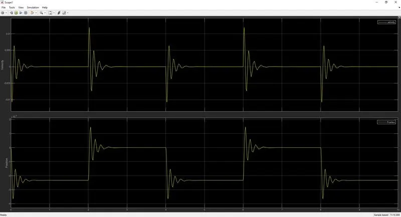
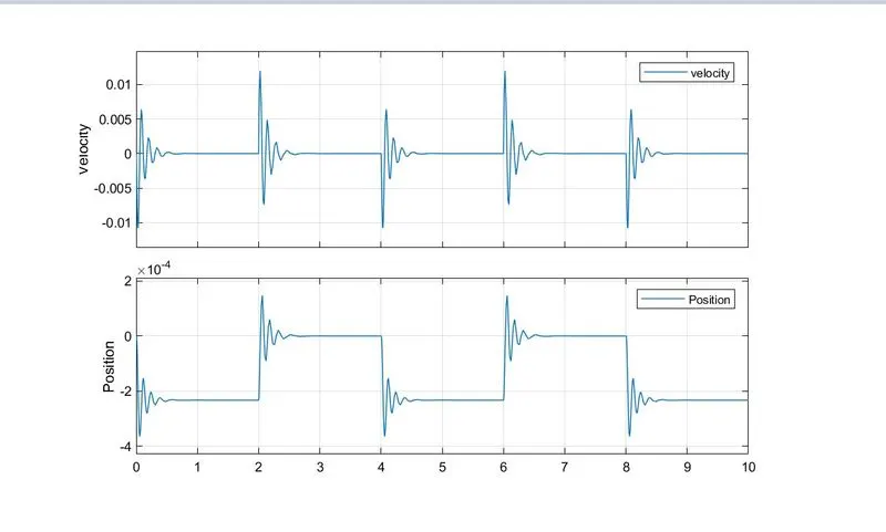
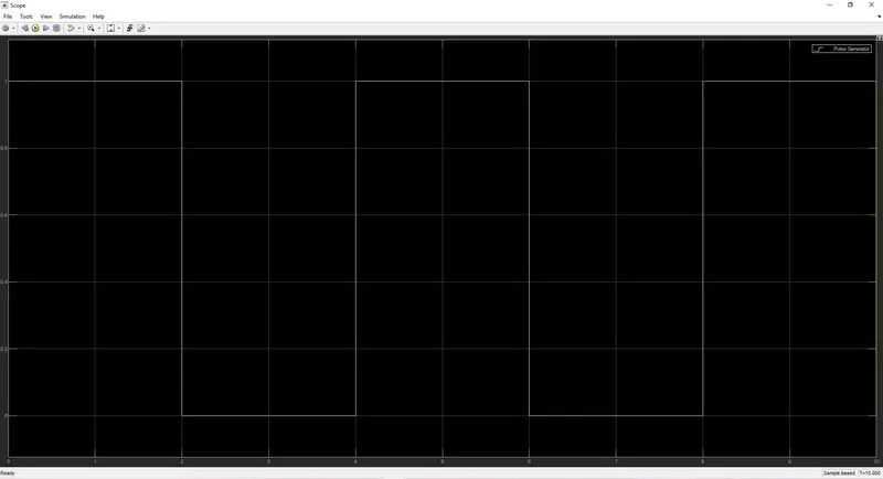
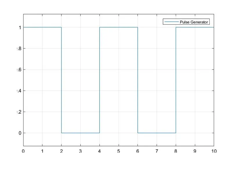
In the above chart we can see that the switch is shut for 2 sec after that switch is open. Amplitude is equivalent to 0 methods the switch is shut. We can likewise see that the clapper strings at regular intervals
2)Use a thermistor to sense the temperature of a heater & turn on or turn off the fan as per the below conditions:
Explanation of Model and Output
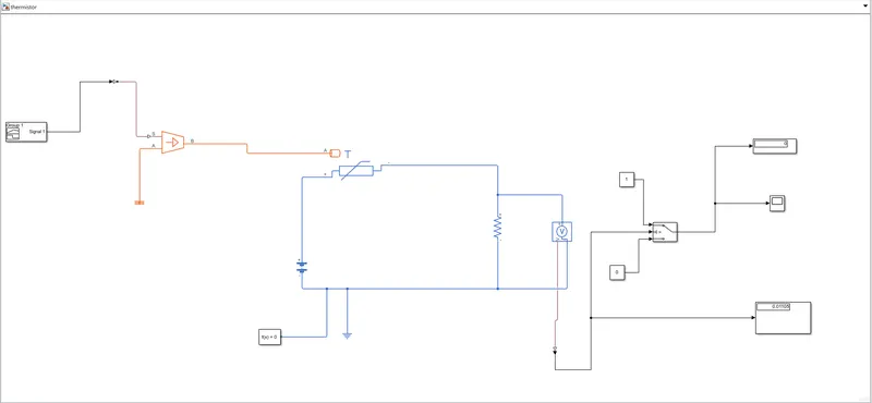
The above model shows the thermistor is utilized to detect the temperature and switch is utilized to begin and stop the fan.
1. We, first and foremost, add thermistor (NTC) block. The port (T) is associated with a controlled temperature source block. The one port is associated with the thermal reference and one more port is associated with converter.
2. The temperature difference is set by the actual signal port (S)which is associated with signal builder block with assistance of Simulink-PS converter. This converter is utilized in light of the fact that we require actual physical signal for temperature source input. Our input signal given to signal builder is Simulink signal.
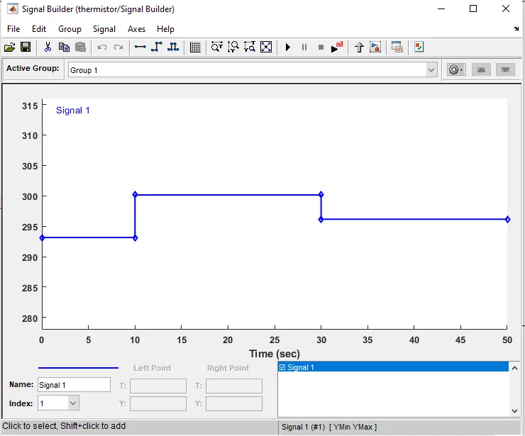
3. In signal developer we made an info signal for framework. According to given condition as follow
0 - 10 sec - temperature is 293.15 k (20℃)
10 - 30 sec - temperature is 300.15 k (27℃)
30 - 50 sec - temperature is 296.15 k (23℃)
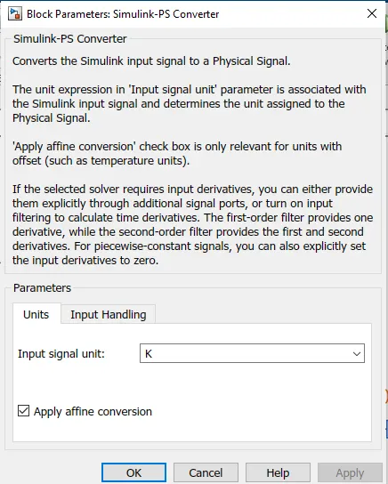
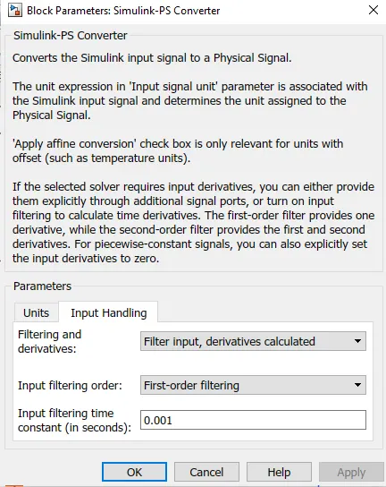
4 . Here the temperature is converted to kelvin because the signal converter didn’t have the option of degree Celsius. Otherwise, there is another option, Apply Affine Conversion, also gave input signal unit is kelvin. Also selected solver requires input derivatives, you can either provide them explicitly through additional signal ports, or turn on input filtering to calculate time derivatives.
5. The battery and voltage sensor are connected in series and resistor is connected in parallel to voltage sensor. The solver arrangement is additionally used to indicate the solver parameter. The electric reference is likewise used to ground the electric framework.
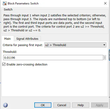
6 . The voltage sensor is connected to switch to control the fan with the help of PS-Simulink converter to convert signal in Simulink input. After that we use scope to decide threshold value of switch. Also, we connected the display to show the last simulation value so we can decide our threshold value with the help of PS- Simulink converter.
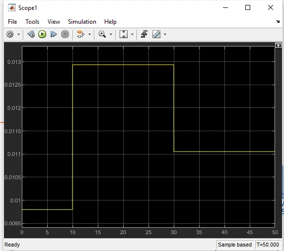
7 .In the switch decided threshold value. If the temperature is above the threshold limit, then it gave '1' as output which means fan switch on and if the temperature is below the threshold limit, then I gave '0' as output which means fan switch off.
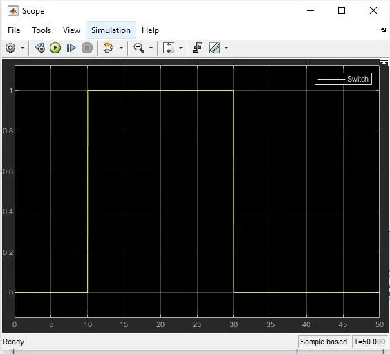
In above graph we can saw form 0-10 sec signal is '0' at that time the temperature was 20℃ which is below 25℃ mean fan should be switch off. After that from 10-30 sec signal is '1' because in this time the temperature was 27℃ which is above 25℃, fan is switch on. At the end from 30-50 sec signal is '0'means the temperature was 23℃ which is below 25℃ so the fans was switched off.
Conclusion:
We can conclude that from the above output results of our Simulink model for solenoid operated heaters give correct output and satisfy with all input conditions.