Week -2
Aim :
1.To make model for simulink block using doorbell.
2.To make simulink model using thermistor to sense temperature of heater & turn on and turn off the fan.
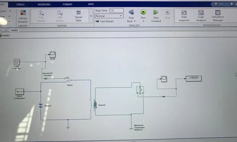
The above image depicts the working circuit of the electronic doorbell.When the switch is turned on then the circuit becomes active the solenoid activates the plunger which in turn hits the bell.
The solenoid is a simple electical device that converts the electrical energy to mechanical work.When an electrical current is introduced,a magnetic field forms around the coil which draws the plunger in,The coil is made of many turns of tighly wounded copper coil.When an electric current flows through this wire,a strong magnetic field/flux is created.
Blocks used:
1. scope : Displays the signal generated (or) generates a graph.
2.Pulse generator :It generates a square wave pulses at regular intervals.The block wave form parameters altitude,pulse width,period and phase delay determines the shape of the out put wave form.
3.Solver Configuration : Each physical network is represented by a connected simscape block diagram requries solver setting information for simulation.The solver configuration block specifies the solver parameter the model needs before you can begin simulation.
4.Solenoid :It represents the electrical characteristics and generated force for the solenoid.
5.Ideal translational motion sensor :It is a sensor block represents a device that converts an across variable measured between two mechanical translational nodes into a control signal proportional to velocity or position.
6.Switch : The switch block models a switch controlled by an external physical signal.If the externl physical signal is greater than the value specified in the threshould parameter,then the switch is closed other wise the switch is open.
7.Battery:The battery block implements a generic dynamic model that implements the most type of rechargable batterys.
8.Simulink-PS converter :This block converts the input simulink signal to the physical signal.Use this block to connect simulink sources or other simulink blocks to the input of the physical network.
Explanation of the model and the output:
1.Firstly,the pulse generator block is used to give signals like amplitude,pulse width,period and phase delay to determine the shape of the output length.Scope is used see graph of the wavelength.
2.After that simulink-ps converter is used to convert the signal input to physical input and send to switch block.
3.To complete the circuit the battery,switch and solenoid blocks are used to connect eachother.The electric reference is used has a ground.All systems are connected in series.The solver configuration block is used to specify the solver configuration.
4.The mechanical part of solenoid is connected to the ideal translational motion sensor because the motion of the clapper is translational and for ground the mechanical translation reference is used.
5.The scope is connected to the ideal translational motion sensor to see output graph of plunger motion,the output has follows.
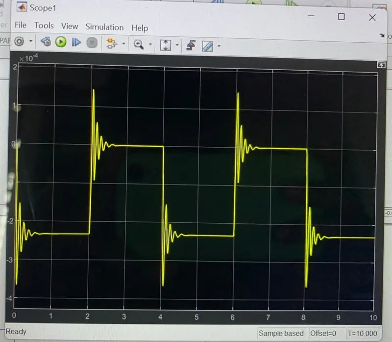
In the above graph we can that the switch is open for 2 sec and close for 2sec.
Conclusion:
Therfore simulink model of doorbell using solenoid block is successfully shown.
Objective 2 :
THERMISTER :
A Thermister is a resistance thermometor or a resistor whose resistance is dependent on temperature. The term is the combination of thermal and resistor.
There are two types of thermistors they are Positive Temperature Coefficient (NTC) and Negative Temperature Coefficient (NTC) when the temperature increases then resistance decreases and conversly temperature decreases then resistance increases.This type of thermister is used the most A PTC thermistor works very little different,When the temperature increases then resistance increases,and when temperature decreases then resistance decreases,This type of thermistor is generally used has fuse.
Blocks used:
1.Switch : The switch block models a switch controlled by an external physical signal.If the externl physical signal is greater than the value specified in the threshould parameter,then the switch is closed other wise the switch is open.
2.Battery:The battery block implements a generic dynamic model that implements the most type of rechargable batterys.
3.Simulink-PS converter :This block converts the input simulink signal to the physical signal.Use this block to connect simulink sources or other simulink blocks to the input of the physical network.
4.Signal builder :This block allows you to create interchangable groups of piecewise linear signal sources and use them in the model.You can switch the signal groups into and out of the model to facilitate testing.In the signal builde window create signals and define output waveforms.
5.Temperature Controlled Source :This block represents an ideal source of thermal energy that is powerful enough to maintain the specified temperature differences across the source regardless of heat flow consumed by the system.
6.Thermistor :This block represents an NTC thermistor block which senses the temperature with respect to time.
7.Voltage sensor block: This block represents an ideal voltage sensor,that is a device that converts voltage measured between two blocks of an electrical circuit into a physical signal proportional to voltage.
8.Electrical Reference : This block represents electrical ground.Electrical conserving ports of all the blocks that are directly connected to the ground must be connected to electrical reference block.A model with electrical elements atleast contain one electrical reference block.
9.Constant :This constant block generates a real constant value signal.Use this block to provide a constant value signal input.
10.Displays the signal generated (or) generates a graph.
Explanation model and output:
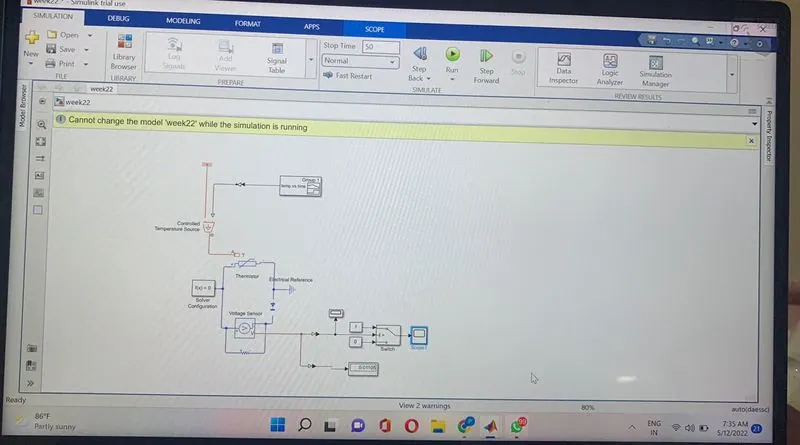
The above model shows the thermmistor is used to sense the temperature and switch is used to start and stop the fan.
1.Firstly we add a thermistor NTC block,the part T is connected to the controlled temperature source block,The block one port is connected to thermal reference and another port is connected to converter.
2.The temperature diffference is set by the physical signal port,which is connected to signal builder with the help of simulink-ps converter.This converter is used because we require physical signal for temperature source input.Our input signal given given to signal builder is simulink signal.
3.In signal builder we created and input signal for the system
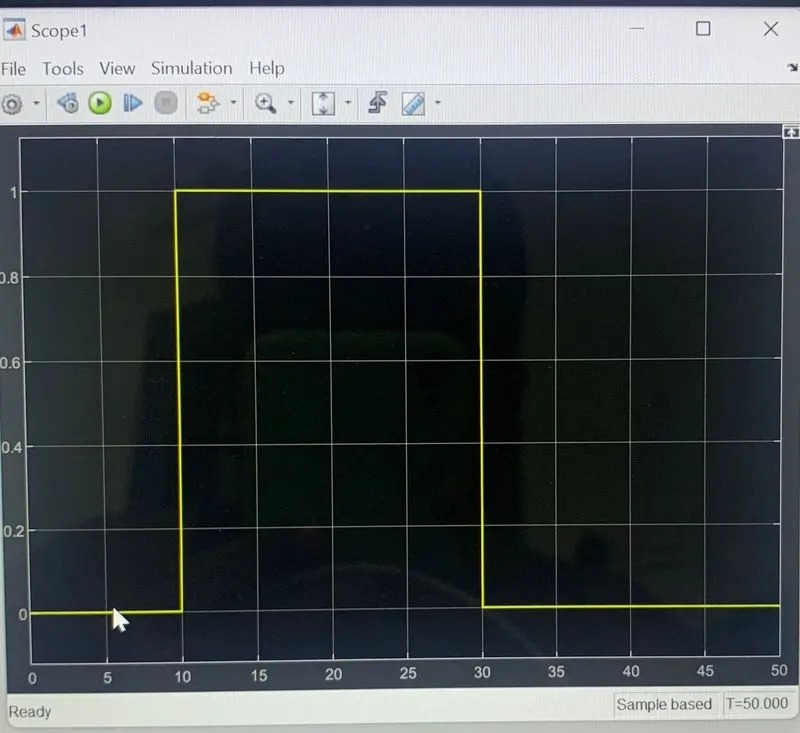
(i) 0-10sec - temperature is 293.15k(20 C)
(ii) 10-30sec -temperature is 300.15k(27 C)
(iii)30- 50sec - temperature is 296.15l(23 C)
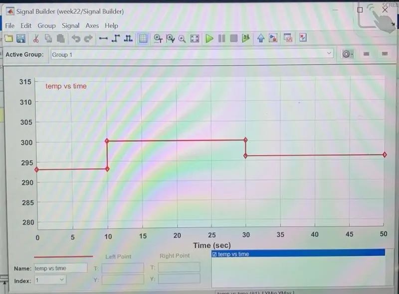
4.Here the temperature is converted to kelvin because it does not have the option to convert to degree celsius.Otherwise there is another option apply affine conversion,also give input signal unit in kelvin,also selected solver requries input derivates,you can either provide them explicitly through additional signal ports or turn on input filtration to calculate derivatives.
5.The battery and voltage sensors are connected in series and resistor is connected in parallel to voltage sensor.The solver configuration is also used to specify the solver parameter.The electrical reference is also used to ground the electric system.
6.The voltage sensor is connected to switch to control the fan with the help of ps-simulink converter to convert signal in simulink input.After that we use scope to decide threshould value of switch.Also we connected the display to show the last simulation value so we can decide our threshould value with the help of PS-simulink converter.
7.In the switch decided threshould value.If the temperature is above the threshould limit then it gave '1' as output which means fan switch on and if the temperature is below the threshould limit then i gave '0' has output which means fan switch off.
8.At the end of the system scope is connected to output for fan on or off.We run the simulation for 50sec because we take time limit in signal builder as 50 sec so we can get the following output.
Conclusion:
We can conclude that from the above output results of the simulink model for solenoid operated heaters give correct output and satisfy with all input conditions.