Week -2
CASE-1
Make a Simulink model of Doorbell using solenoid block.
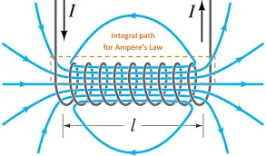
The solenoid simply works on the principle of “electromagnetism”. When the current flow through the coil magnetic field is generated in it, if you place a metal core inside the coil the magnetic lines of flux is concentrated on the core which increases the induction of the coil as compared to the air core.
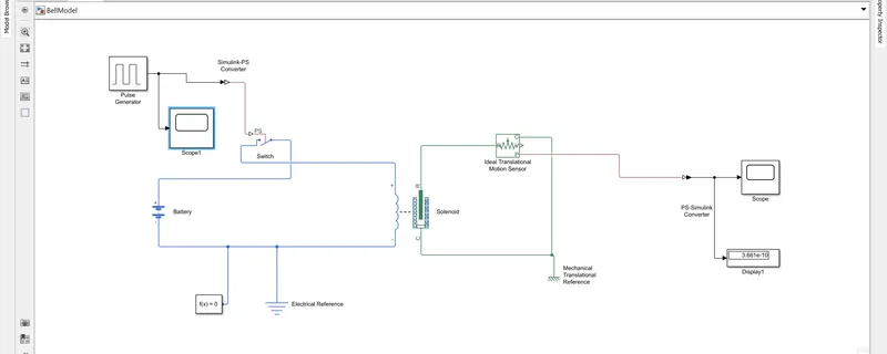
Contents : Pulse generator, Ideal Translational Motion Sensors , PS switch ,Ps to simulink Converters ,Simulink to ps converter, Scope , Solvers configrurations , Solenoid coils , Battery .
Pulse Genrators : The Pulse Generator block generates square wave pulses which is the signals is suitable or not for inputs .
Ideals translationals motion sensors: The Ideal Translational Motion Sensor block represents a device that converts an across variable measured between two mechanical translational nodes into a control signal proportional to velocity or position.
PS switch: the inputs of the ps switch is connect to simulink to ps converter and pulse genrators the switch is close of every 2 sec .
At point 1 : Time of 0 sec - temperature is 293 k
Simulink to ps converter : the block is used to convert simulink signals into physicals signal
Solvers configrations: the solvers configrations blocks represents to solve the expressions used during the simulations .The solvers configratioins are used into each physicals network during simulations .
Scope : the slope is used to represents the plot movements of the plungers after the ps switch is close at every 2 sec .
Display: the blocks which is used to shows the outputs value .
Solenoid coils : the solenoid coils are used to convert mechanical energy into electricals energy with linear movements.
SIMULINK MODELS AS SHOWN BELOWS :
OUTPUTS RESULTS-1
The scope of the inputs pulse genrators shows the inputs pulse is corrects or not for plots the switch is close for 2 sec .
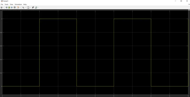
OUTPUTS RESULTS-2
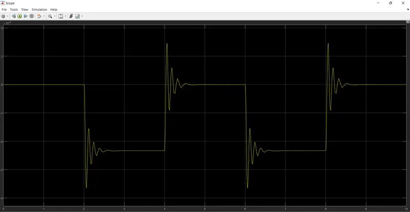
The results of this plots shows every 2 sec the switch will be close the plungers is pull down and hits to bell and sound rang the condition is being satified.
CASE-2
Use a thermistor to sense the temperature of a heater & turn on or turn off the fan as per the below conditions:
Temperature source: 20 °C from 0 to 10 seconds, 27 °C from 10 to 30 seconds, 23 °C from 30 to 50 seconds
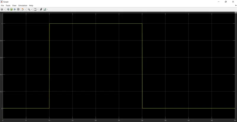
Fan conditions: ON if the temperature above 25 °C, OFF otherwise.
Block used :
- Controlled temperature source
- Signals builder
- Battery
- Resistor
- Electrical reference
- Solvers configrations
- Switch
- Constants
- Scope
- Display
- Ps to simulink converter
- Simulink to ps converter
Simulink model :
Explanations :
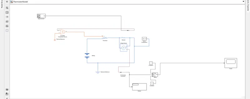
Now here we used the following block which are shown in above list thermister are connected extactly in series with battery which is used to fed the power in ckt as we shown . here also we shown resistors in which across connected a voltage sensors which is used to sense the volage across the resistor at least one solver is to be connected at physical network for grounding purpose we connect electrical referance to part of electrical ckt.
The display which is used to shows the the voltage acros the resistors at appling different temp conditions and also a logics switch which is also connected to to volatge sensors of v port the switch has to constant 1 - ie. 1 and constant 2 -n ie. 0 and switch output which is connected to scope which is used to show a graphiclals anaysis .
The signals builder block build the signals first we open the dialouge box and double click on siganal builders block click on new select the option custum and place here we reqired diff time value and temperature ranges as per given conditions after click ok and here we seen the graph of inputs signlas which is build by signals builder.
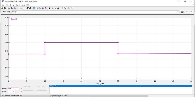
At point 1 : Time of 0 sec - temperature is 293 k.
At point 2 : Time of 10 sec - temperature is 293 k.
At point 3 : Time of 10 sec - temperature is 300 k.
At point 4 : Time of 30 sec - temperature is 300 k.
At point 5 : Time of 30 sec - temperature is 296 k.
At point 6 : Time of 50 sec - temperature is 296 k.
Simulink to ps converter : The block is used to convert simulink signals into physicals signal.
Solvers configrations: The solvers configrations blocks represents to solve the expressions used during the simulations .The solvers configratioins are used into each physicals network during simulations.
Controlled temp source : The controlled temp source block repreents the ideal source of thermal energy is powerful to enough to maintain specified temp difference .
Result :-