Week-2 Challenge on Doorbell and Thermistor
Week 2 Challenge
Aim: To build models of a Doorbell using a solenoid and a thermistor output reliant fan.
Objectives: 1) Make a Simulink model of Doorbell using solenoid block with the following details:
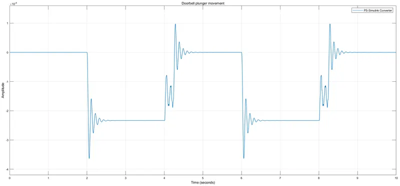
In the above arrangement, when the switch is closed the electromagnet receives electrical power from the battery and pulls the metal arm to hit the bell producing sound. Create a situation where the switch is closed for 2 seconds and then released. Observe the physical movement of the plunger.
2) Use a thermistor to sense the temperature of a heater & turn on or turn off the fan as per the below conditions:
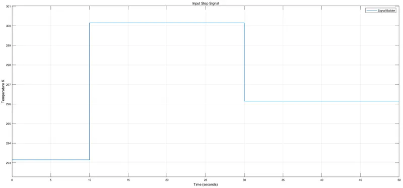
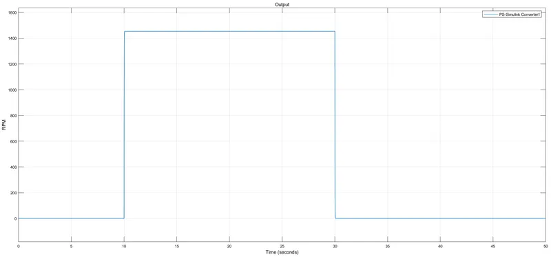
Temperature source: 20 °C from 0 to 10 seconds, 27 °C from 10 to 30 seconds, 23 °C from 30 to 50 seconds. Fan conditions: ON if the temperature above 25 °C, OFF otherwise.
Part 1
In this part, we have to build a Simulink model of a doorbell using a solenoid. Lets know the steps involved:
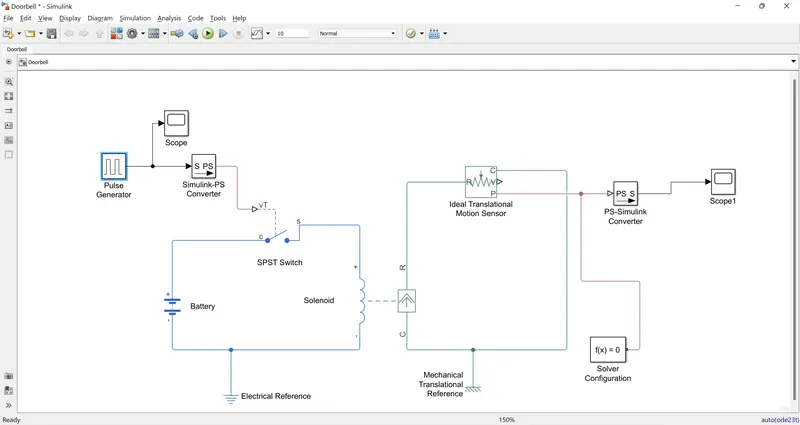
Component blocks in use: A pulse generator, a SPST switch, a battery, a solenoid, an ideal translational motion sensor, electrical and mechanical translational references, Simulink-PS and PS- Simulink converters, solver configuration and scopes.
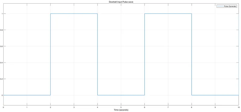
1)So we have a solenoid and we have to build our model around it. It’ll have two parts- input and output. On the input side, we will require an input signal, which shall be provided by a pulse generator. The parameters of the pulse generator are set as below:
The period states the total time (on and off) of a pulse of the wave. To satisfy our condition of switch closure for 2 secs we take period of 4 secs and pulse width as half of it i.e 2 secs
2) The output of our pulse generator shall be our input to a switch that shall open and close accordingly. However, pulse generator being a Simulink block and our switch being a Simscape block will require a Simulink-PS converter. Our switch in the given model is a SPST switch. It will close for all the high values of the pulse generator, allowing flow of current from the battery to the solenoid.
3) Now, the ‘s’ port of the switch is connected to the ‘+’ terminal of the electrical part of the solenoid. The ‘c’ port meanwhile is connected to the ‘+’ terminal of a battery. The other ends of the battery and solenoid are connected to complete the electrical connections. An electrical reference is also connected across this to secure the connection.
4) Moving onto the output part. Based on the inputs from the electrical part, the solenoid plunger will move accordingly. For a closed switch, the plunger will make a movement. To view this movement an ideal translational motion sensor is used. The ‘R’ port of the sensor is connected to the ‘R’ port of the solenoid whereas the ‘C’ port is connected to the ‘C’ of solenoid. Also, a mechanical translational reference and a solver configuration block are connected.
5) To view the output a scope is used. However, scope being a Simulink block requires a conversion of the physical signal from ideal translational motion sensor. Hence, a PS-Simulink converter is used.
The Model
https://drive.google.com/file/d/1dHgb4gHvs4j6P0WjZRx8r_InK4z--Ga8/view?usp=sharing
Plots
Part 2
For this part, we have to use a thermistor to sense the temperature of a heater and turn on or off the fan. Let’s know the steps involved:
Component blocks in use: a signal builder, a controlled temperature, a thermistor, a battery, a resistor, a voltage sensor, a HDL switch, constant blocks, a controlled voltage source, a DC motor, an ideal rotational motion sensor, electrical & mechanical rotational reference, Simulink-PS and PS- Simulink converters, solver configuration and scopes.
1)As evident, our model shall be based around a thermistor with input and output sides. For the input side we would require signals that could give the thermistor the specified temperature conditions. We use a signal builder for the same. The specified conditions as stated in the objective are input into this block. The output is to be connected to a controlled temperature source but a Simulink-PS converter is required. Also, a scope is connected to view the signal.
2) The Controlled Temperature Source block represents an ideal source of thermal energy that is powerful enough to maintain specified temperature difference across the source regardless of the heat flow consumed by the system. The ‘B’ port of this block is connected to the Thermal port of the thermistor. The ‘A’ port though is connected to a thermal reference.
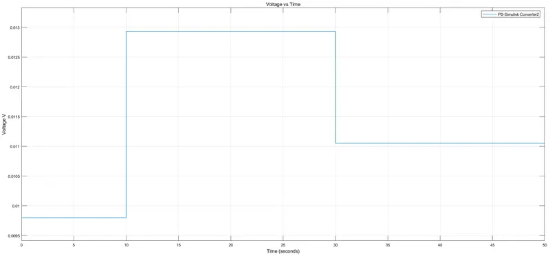
3) A battery is connected to the thermistor as a source of power. A resistor is also connected with a voltage sensor to know the corresponding voltage values against temperature. A electrical reference and a solver configuration complete the input side of the thermistor.
4) The voltage value corresponding to 25° C is something that we need to specify as a threshold to our switch to switch the fan on or off. For this, we connect a display to the output of our voltage sensor and obtain the value as 0.01196 V for a temperature of 25° C.
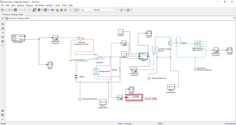
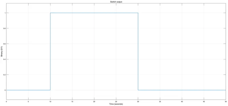
5) On the output side we first place a ‘HDL’ switch which is nothing but a switch working on the if/else condition. In our case, we require the fan to turn on for temperatures exceeding 25° C else, it should remain closed. Hence, we specify the threshold for the switch as 0.01109 and connect constant blocks of value 1 & 0 across the inputs 1 and 2. For voltage sensor output exceeding threshold, input 1 will be connected to output and the fan will switch on and vice versa.
6) Now, the switch is to be connected to a DC motor, but we need a controlled voltage source to regulate the voltage across the motor. Hence, a controlled voltage source block is placed after the switch. Also, a solver configuration is used to perform the calculations.
7) Now, a fan needs to be connected to the motor. For this, we use the ideal rotational motion sensor block. A mechanical rotational reference is also connected to secure the connection. A scope is connected at the output of motion sensor block to view the movement.
The Model
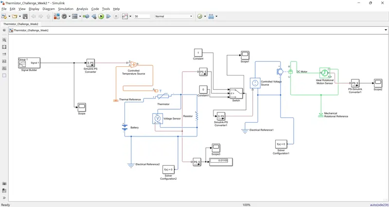
https://drive.google.com/file/d/1ieKW_3-8HM46QAcL6N2KBdno-USZrDbE/view?usp=sharing
Plots