Week -2
Aim 1: Make a Simulink model of Doorbell using solenoid block. Create a situation where the switch is closed for 2 seconds and then released. Observe the physical movement of the plunger.
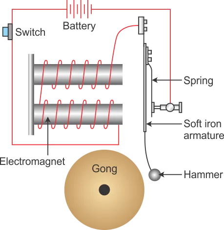
Theory: The electrical doorbell is simple circuit that triggers a sound on the completion of circuit by pressing the button. Principle of electromagnetism is used. Electromagnet is the type of magnet in which the magnetic field is produced with the help of an electric current.
In an electric source such as battery is used to power the electromagnet in the electric bell. In the model the electromagnet is a solenoid. A push switch completes the circuit. By pressing this one can operate the bell. When the switch is pressed the circuit gets completed. The arm called hammer is attached to an iron strip which is attracted to the electromagnet when the circuit gets completed.
As the arm is attracted to the magnet it loses connection with the contact pin and the circuit breaks and magnet loses its power and arm moves back to original position where it again comes in contact with the contactor pin in turn making the circuit complete again. This process happens rapidly thus causing multiple hits of Hammer on the bell, thus, making the bell ringing sound.
Model Explanation:
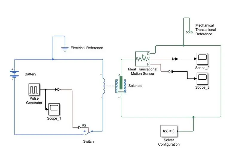
A pulse generator is used to give the input that depicts 2 sec of pressing and 2 sec of letting go of bell. The Simulink signal is converted to PS and given to PS switch. The switch is turned on or off as the pulse oscillates between 1 and 0.
A solenoid is connected to the switch and a Battery. As the circuit is completed current passes through the solenoid block and a motion is imparted on the physical system of solenoid represented by translation motion ports R and C. Port C is connected with mechanical reference.
The R and C ports of Solenoid are connected with the R and C ports of the Ideal Translational Motion Sensor which will read the motion imparted by the Solenoid valve. Scope to see the Velocity and Displacement is connected to the Ideal Translational Motion Sensor.
Blocks Used:
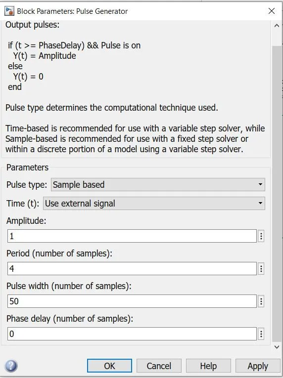
- Pulse generator: Input parameters are set for this block as “Period:4” “Pulse Width:50” representing that one sample is of 4 seconds, and pulse width is of 50% e. 50% active and rest inactive - 2 seconds of active and rest inactive. Scope can be connected to Pulse generator to see the output graph which will oscillate between 0 and 1 in 2 secs intervals.
- Physical System Switch: The physical system Switch block accepts PS input. And Uses default threshold set to “0.5”. Signal of 0 means Off and 1 means ON .
- Solenoid: Solenoid has two systems. Electrical and Mechanical. Electrical signal is connected to a battery and an Electrical reference. And Mechanical system to the motion sensor.
- Ideal Translational Motion Sensor: The mechanical system is connected to the Ideal translational motion sensor block which senses the motion of solenoid lever. Ports R and C are mechanical translation ports. C is connected to a Mechanical reference. Velocity and Displacement Scope can be obtained from the Ideal translation motion sensor which represents the motion of the hammer on the bell.
- Solver Configuration: A solver Configuration must be given to a System to define a Solver where Simulations is performed.
Results:
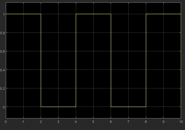
- Scope 1 shows that the pulse generator does its work of giving 2 secs of Pressing of the bell
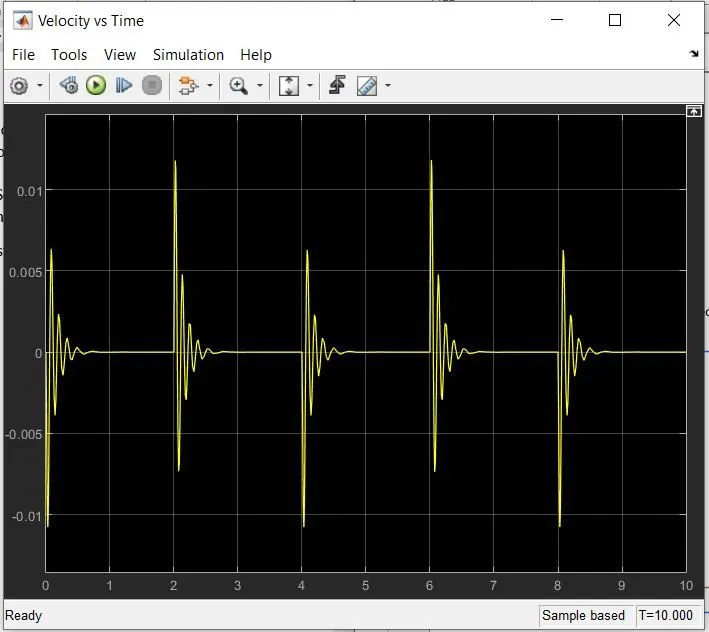
- Velocity vs Time Graph shows that the Solenoid moves the Hammer every 2 seconds.
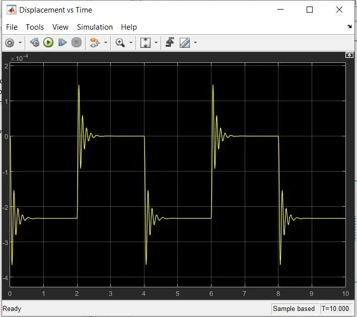
- Displacement vs Time Graph shows that every 2 seconds the Solenoid Valve gets activated and the position oscillates between extreme ands alternate
Scope 1: Signal input, 2 seconds on/off.
Displacement vs Time
Velocity vs Time
NOTE:
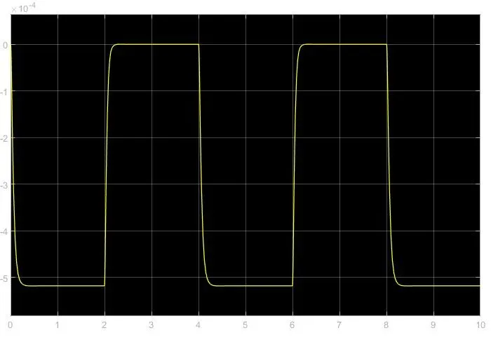
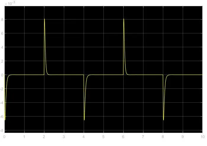
If we want to reduce the distrubances in theabove plats then we can decrease the stiffness and increase the damping coeff
Spring Stiffness (K) = 100
Damoing coeff (C) = 5
Displacement vs Time with updated Parameters
Velocityvs Time with updated Parameters
---------------------------------------------------------------------------------------------------------------------------------------------------
AIM 2:
Use a thermistor to sense the temperature of a heater & turn on or turn off the fan as per the below conditions:
Temperature source: 20 °C from 0 to 10 seconds, 27 °C from 10 to 30 seconds, 23 °C from 30 to 50 seconds
Fan conditions: ON if the temperature above 25 °C, OFF otherwise.
Theory:
What is a Thermistor?
A thermistor is a type of resistor whose resistance is strongly dependent on temperature. Thermistors act as a passive component in a circuit. They are an accurate, cheap, and robust way to measure temperature.
Working Principle:
The working principle of a thermistor is that its resistance is dependent on its temperature. We can measure the resistance of a thermistor using an ohmmeter. If we know the exact relationship between how changes in the temperature will affect the resistance of the thermistor – then by measuring the thermistor’s resistance we can derive its temperature.
Model Explanation:
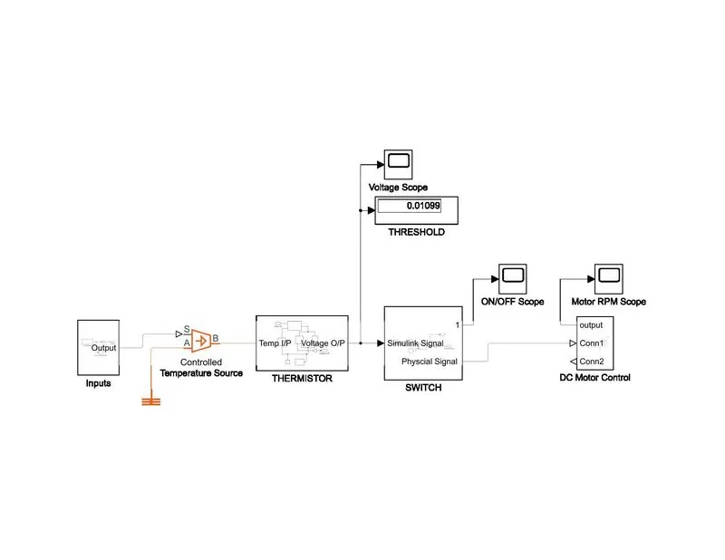
The Model is divided into 4 subsystems, namely Inputs, Thermistor, Switch and DC Motor.
The Input subsystem generates Input using Signal builder as per requirement, in this case distributed in 50 seconds time frame. Thus, the stop time is set to 50 sec.
Further the controlled temperature source sends thermal signal to Thermistor. Resistance of thermistor changes according to the input signal. A resistor is connected in series. A voltmeter is connected in parallel to the resistor. Both of these are connected to get the threshold voltage.
The voltage signal is converted to Simulink signal and sent to switch. Switch is connected to Constanta 1 and 0 indicating On and Off signal respectively. The Threshold value achieved from voltmeter is fed in switch to the controlled output signal.
Output signal from Switch is converted to PS and sent to Controlled Voltage source, and further to DC Motor. DC motor block has electrical as well as physical system. The electrical system is connected with Controlled voltage source and Physical signal is connected to Ideal rotational motion sensor that acts as a measurement for whether the Fan is On/Off.
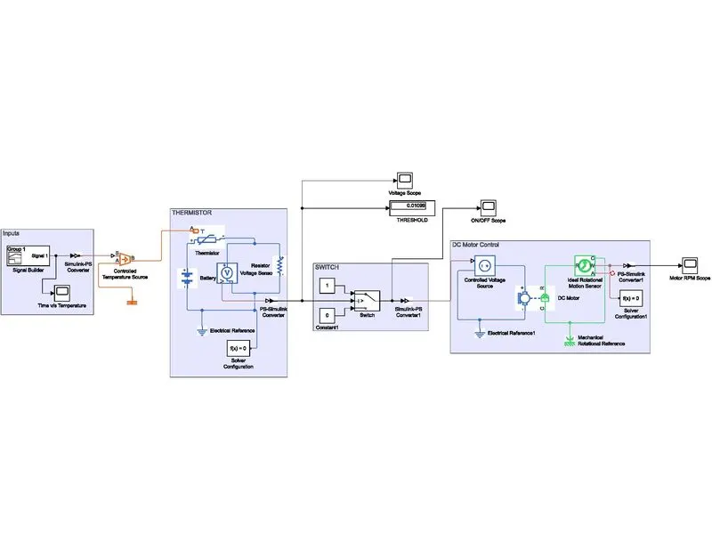
Blocks used:
- For Inputs:
- Signal Builder: The Signal Builder block allows you to create interchangeable groups of piecewise linear signal sources and use them in a model. In the Signal Builder window, create signals and define the output waveforms. Signal is built as per given input in Kelvin scale.
- Simulink PS-Convertor: First Order Filtering is used.
- Controlled Temperature Source: The Controlled Temperature Source block represents an ideal source of thermal energy. S port is given Physical signal input, B port is the temperature output, and A is connected to Thermal reference.
- For Thermistor:
- Thermistor: Thermistor is given a temperature input, that will vary in specified time intervals. Threshold Value set in the Thermistor Block.
- Battery: Connected to thermistor in series set to default parameter.
- Resistor: Connected in series with battery and set to default parameters. Resistor and Voltage sensor is connected to find out the threshold voltage, which is triggering value to make fan on/off. Here it is given as 25 C.
- Voltmeter: In parallel with Resistor. A scope to view the voltage fluctuation with the temperature can be seen in the scope and the threshold can be viewed in the Scope. The threshold is used as input value for the Switch.
- Electrical reference: Every separate Electrical system must have an electrical reference.
- Solver Configuration: Every electrical system must have one solver configuration in each model.
- PS-Simulink convertor: Next the Signal goes to a Switch, so the PS has to be converted into Simulink signal.
- For Switch:
- Switch: The first and third input ports are data ports, and the second input port is the control port. Constant 1 is connected to port 1 and Constant 0 is connected to port 3, threshold value is set as that which is achieved from Voltmeter output.
- Constants: Used as Inputs.
- Simulink-PS Convertor – The Simulink signal needs to be converted to PS signal as it is not going as Voltage.
- For DC Motor:
- Controlled Voltage source (foundation library/Electrical/Electrical Sources): Controlled voltage source is used to pass voltage to the DC Motor according to the signal received. Electrical reference is connected in series in the connection.
- DC Motor: Positive and Negative ports are connected to the controlled voltage source positive and negative ports respectively. C and R are the mechanical translational ports. Mechanical rotational reference is attached in series with this connection between C ports.
- Ideal Rotational Motion Sensor: This block is used to sense the rotational movement generated by the DC motor. R and C ports are connected with the R and C ports of the DC motor respectively, with Mechanical reference port between C ports.
- Solver Configuration: Every mechanical system must have one solver configuration in each model.
- PS-Simulink Convertor – The PS is converted to Simulink signal so that it can go to scope.
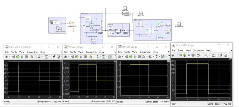
Results:
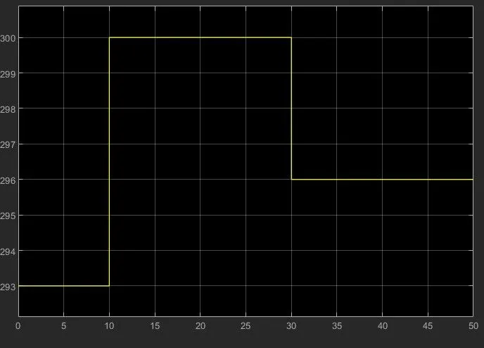
- Time vs Temperature scope shows that input is according to requirement i.e. 293K till 10 seconds, 300K for next 20 seconds and 296K for rest 20 secs.
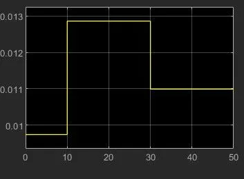
- Voltage Scope shows that the voltage output is in accordance with the temperature input. And Threshold value can be approximately seen on the graph.
- ON/OFF scope shows that the threshold voltage works properly and it switched between ON and OFF at exact time periods as per requirement i.e. as the temperature is above 298K.
- Motor RPM scope is same as ON/OFF scope which shows the fan gets On and off according the requirement.
Time vs Temperature:
Voltage Sensor:
Switch:
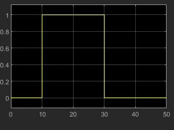
Fan Motor:
Learnings:
- One solver configuration for each type of simulation. i.e. 2 in this model since it is an electro-mechanical simulation.
- Each system requires a reference, i.e. Electrical reference for electrical system, Mechanical Reference for mechanical system, etc.
- How switch works. Concept of threshold Voltage .
- Concept of thermistor and controlled output from thermistor.
- How to make subsystems in Simulink.