Week 2- 2R Robotic Arm Challenge
INDEX
1. AIM
2. OBJECTIVE
3. INTRODUCTION
4. GOVERNING EQUATIONS
5. MATLAB PROGRAM
5. EXPLANATION OF THE PROGRAM
6. RESULT
7. CONCLUSION
1. AIM
Write a program in Matlab to simulate the forward kinematics of a 2R Robotic Arm.
2. OBJECTIVE
1. Write a program to simulate the motion
2. Create an animation file of the plot
3. INTRODUCTION
Robotic arms are machines that are programmed to execute a specific job or task quickly, efficiently, and extremely accurately. A schematic diagram of the robotic arm is shown in figure 1.1. A typical industrial robot arm includes a series of joints, articulations, and manipulators that work together to closely resemble the motion and functionality of a human arm. Manipulator/end effector movement determines the workspace where the robotic arm can be applicable. Kinematics is the analysis of motion without considering the forces. Forward kinematics refers to the use of the kinematics equation of a robot to compute the position of the end effector from specified values for the joint parameters.
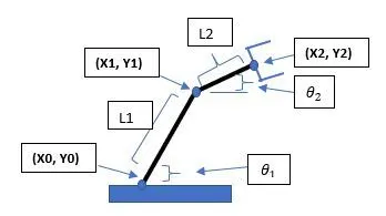
Figure 1.1 2R Robotic arm schematic diagram
4. GOVERNING EQUATIONS
If we know the geometry of the robot and all its joint points, we can do the math and figure out the position and orientation of any point on the robot. i.e, if we can able to figure out how the robot is going to move then we can figure out its workspace. Equations are shown below for the calculation of forward kinematics of 2R robotic arm.
`X0, Y0`=0,0, At the base
`X1=L1.cos(θ1)`, X-coordinate at the end of Link 1
`Y1=L1.sin(θ1)`, Y-coordinate at the end of Link 1
`X2=L2.cos(θ2)`, X-coordinate at the end of Link 2
`Y2=L2.sin(θ2)`, Y-coordinate at the end of Link 2
Where,
`L1`-First Link of 2R Robotic arm
`L2`-Second Link of 2R Robotic arm
`θ1`-Angle between Link 1 and base
`θ2`-Angle between Link 2 and base
`X0, Y0`- Coordinates at the base
`X1, Y1`-End coordinates of Link 1
`X2, Y2`-End coordinates of Link 2(End effector)
5. MATLAB PROGRAM
clear all
close all
clc

%inputs
L1=1;
L2=0.5;

%angle
theta1=linspace(0,90,10);
theta2=linspace(0,90,10);

%F lopp for executing the differnt positions of robotic arm
counter=1;
for i=1:length(theta1)
   THETA1=theta1(i);
   for j=1:length(theta2)
   THETA2=theta2(j);
   %Coordinates
   x0=0;
   y0=0;

   x1=L1*cosd(THETA1);
   y1=L1*sind(THETA1);

   x2=x1+L2*cosd(THETA2);
   y2=y1+L2*sind(THETA2);

   %Plotting of line
   figure(counter)

   %First link plot
   plot([x0 x1],[y0 y1],'linewidth',3,'color','b');

   %second link p[lot
   hold on
   plot([x1 x2],[y1 y2],'linewidth',3,'color','r');

   %graph plotting commands
   axis([-0.1 1.5 0 1.5]);
   title('Forward Kineamtics of a 2R Robotic Arm');
   legend('Link 1','Link 2');
   xlabel('X Axis')
   ylabel('Y Axis')
   grid minor

   %pause video at the interval of 0.3 seconds
   pause(0.3)
   M(counter)=getframe(gcf);
   counter=counter+1;
   end
end

%write the movie file in avi format and save
movie(M)
videofile=VideoWriter('forward_arm_final.avi','uncompressed AVI');
open(videofile)
writeVideo(videofile,M)
close(videofile)
6. EXPLANATION OF PROGRAM:
- Initially, All the input values are defined.
- Use of for loop command for iterating the values of the first arm.
- Again using for command for providing movement to the second robotic arm.
- Plotting all the coordinate values and writing commands for changing the appearance of the contours.
- All figures are assigned to a variable M, one at a time using counter followed by termination of for loop.
- Lastly, the movie command is used to combine all the figures saved in the M file to make an animation/movie and thereafter saved it in .avi format.
7. RESULT
ANIMATION VIDEO OF FORWARD KINEMATICS OF 2R ROBTIC ARM
8. CONCLUSION
MATLAB program executed for different positions of the robotic arm and experienced a practical scenario regarding the functioning of the robotic arm and its workspace.