Week 2- 2R Robotic Arm Challenge
Challenge: 2R Robotic Arm Challenge
Aim: Write a program in MATLAB to simulate the forward kinematics of a 2R Robotic Arm.
Objective:
- Step-wise explanation of your code.
- Mention the errors faced while programming.
- Steps taken to overcome those errors.
- Screenshots showing errors thrown in command window.
The arm like structure of an industrial robot is known as a robot manipulator. The component is responsible for completing the task the robot is programmed to perform. Also known as a robot arm, the manipulator mounts to the robot body and consists of multiple links and joints.
Links are rigid components that connect different sections of the robot arm. Their rigidity provides a solid structure, but joints are necessary for flexibility. As with the human body, robotic joints move in different ways, Facilitating linear, rotary and revolutionary motions. This allow the robot to perform the desired movements within its work envelope.
Hence, We have simulated the 2 Link robot arm, to perform its intended function to reach its maximum capability. The program defines the joint parameters and end effector locations symbolically, calculates and visualizes the forward and inverse kinematics solutions and finds the system Jacobian, which is useful for simulating the motion of the robot arm.
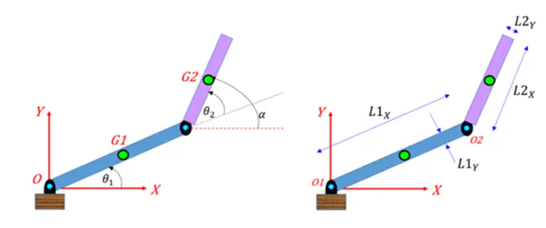
- Step-wise explanation of your code.:
Step 1: Define Geometric Parameters:
Defined length of links
Length of Link 1(l1) = 1;
Length of Link 2(l2) = 0.5;
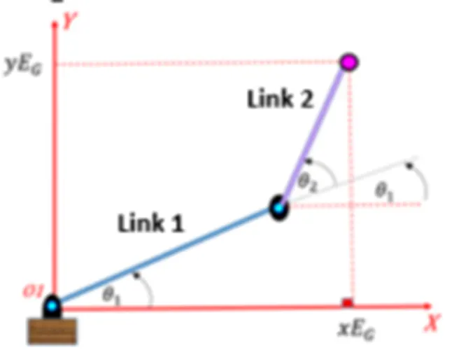
Step 2: Defined X and Y Coordinates of End Effector with Angles:
X0, Y0: The starting point of the link 1 which is attached to base
as the base is fixed. So the starting point is “0”.
X0 = 0, Y0 = 0
X1, Y1: In this case starting point of link 2 is end of the link 1. l1 length of link
and angle between link 1 with base is Ø1
X1 = l1 * cosd(Ø1), Y1 = l1 * sind(Ø2)
X2, Y2: This is case of end point of link 2. l2 length of link and angle between Link 2 and Link 1 is Ø2
X2 = X1 + l2 * cosd(Ø2), Y2 = Y1 + l2 * sind(Ø2)
Step 3: Code for visualize forward kinematics with explanation:
1.Initial code to clear the earlier stored data and clear command window.
Clear all: This command is used to clear all the data stored in the workplace.
Close all: This command is used to close all figures and close plots.
clc : This command clears the command window.
2.We are defining the geometric parameters of the link and define the angle for degree of freedom
The input value for Ø1 and Ø2 is defined by linspace to define the degree of freedom movement of linkage from 0° to 90° with 10 values between the links.
clear all
close all
clc
%Inputs
%Link Lengths details

l1 = 1; %Assuming a length of link 1
l2 = 0.5; % Assuming a length of link 2
theta1=linspace(0,90,10); %Angle between link 1 and base
theta2=linspace(0,90,10); % Angle between link 1 and link 2
no_of_frames = 1;
for i = 1:length(theta1)
T1 = theta1(i)
for j = 1:length(theta2);
T2 = theta2(j);
X0 = 0; % x coordinate of link 1 start point
Y0 = 0; % y coordinate of link 1 start point
X1 = l1*cosd(T1); % x coordinate of link 1 end point
Y1 = l1*sind(T1); % y coordinate of link 1 end point
X2 = X1+ l2*cosd(T2); % x coordinate of link 2 end point
Y2 = Y1+ l2*sind(T2); % y coordinate of link 2 end point

    %Plotting of graph
    plot([X0 X1], [Y0 Y1], [X1 X2], [Y1 Y2],'linewidth',3) %plotting the x and y axis coordinates.
    axis([-0.1 2 0 2]); %plotting the x and y axis coordinate
    pause(0.03); %pause time for each frame
    m(no_of_frames) = getframe(gcf);
    no_of_frames = no_of_frames + 1;
    end
end
movie(m)
videofile = VideoWriter('forward_kinematics.avi','Uncompressed AVI');
open(videofile)
writeVideo(videofile,m)
close(videofile)
%Inputs
%Link Lengths details
l1 = 1; %Assuming a length of link 1
l2 = 0.5; % Assuming a length of link 2
%Angle between the links
theta1 = linspace(0,90,10); %Angle between link 1 and base
theta2 = linspace(0,90,10); % Angle between link 1 and link 2
3. To initialize the frame rate for forward kinematic.
no_of_frames = 1;
4. For continuous movement of arm using “For Loop”
for i = 1:length(theta1)
T1 = theta1(i)
for j = 1:length(theta2);
T2 = theta2(j);
X0 = 0; % x coordinate of link 1 start point
Y0 = 0; % y coordinate of link 1 start point
X1 = l1*cosd(T1); % x coordinate of link 1 end point
Y1 = l1*sind(T1); % y coordinate of link 1 end point
X2 = X1+ l2*cosd(T2); % x coordinate of link 2 end point
Y2 = Y1+ l2*sind(T2); % y coordinate of link 2 end point
Plotting of graph with saving the video file of the program.
plot([X0 X1], [Y0 Y1], [X1 X2], [Y1 Y2],'linewidth',3) %plotting the x and y axis coordinates.
axis([-0.1 2 0 2]); %plotting the x and y axis coordinate
pause(0.03); %pause time for each frame
m(no_of_frames) = getframe(gcf);
no_of_frames = no_of_frames + 1;
end
end
movie(m)
videofile = VideoWriter('forward1_kinematics.avi','Uncompressed AVI');
open(videofile)
writeVideo(videofile,m)
close(videofile)
Note: I am not able to create the video file in web based MATLAB system. Getting error on Frame rate. I tried to do trail and error on the Angle plot and changing coordinate but its not working,
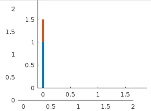
I have attached the PDF file of the code for your reference. Below is the output graph for reference.
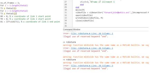
Step 4: Error in the code observed:
The MATLAB is case sensitive programming language due to which observed below error of code not getting executed.
I had typed the "for" command as "For" due to which code was not getting terminated and which resulted in non execution of program and also proper semicolon not provide in the line to complete the code line.
Corrected the "for" command to smaller case and added semicolon where ever neccessary to execute the program.
I have not checked on the loop command and Angle coordinate value which effect graph output. As link starting point will be changing which is not practical scenerio in real built condition.
With Regards,
Vijay B K