Week 2- 2R Robotic Arm Challenge
Question: Write a program in Matlab to simulate the forward kinematics of a 2R Robotic Arm, as shown in the video.
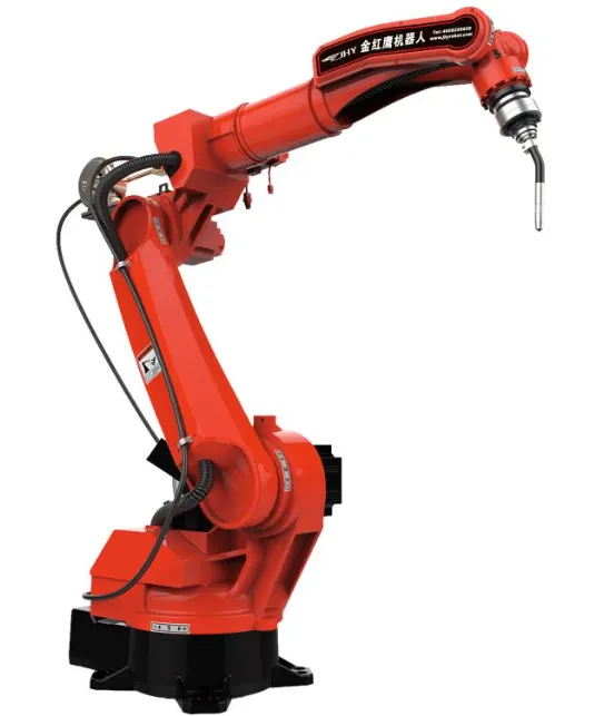
2R Robotic Arm: It is defined as a mechanical arm which consists of Manipulator that act as a welding tool or any machining tool to perform required task. 2R robotics arm consists of 2 links and 2 rotational joints as shown below.The links are usually known as the members that is rigid and further holds the joints parts. The joints are nothing but the movable part in the robotic arm mechanism and this further combined together causes motion of the body.
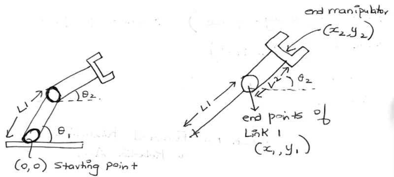
Where L1 is the Length of the Link 1 and L2 is the length of the Link 2 and theta1 is the respective angle that link L1 makes with respect to the horizontal axis and theta2 is the respective angles that Link L2 makes with the horizontal x axis.
Steps of Procedure followed:
Program 1: To understand the working mechanism of the links L1 and L2 of the 2R robotic arm and to verify the formula defining the kinematics of robotic arm
Code Description:
Inputs given:
- Length of the link 1=0.5 m
- Length of the link 2=0.5 m
- Theta of the link 1=40 degree
- Theta of the link 2=20 degree
Coordinates description:
From the representation of the robotic arm and from the geometry of the figure, we can represent the x0, y0, x1, y1, x2 and y2 as follows:
- x0 and y0 is the starting point of the Link L1.
- x1 and y1 is the end point of the Link L1 but it is also the starting point of the Link L2.
- x2 and y2 is the end manipulator coordinates.
Plotting command:
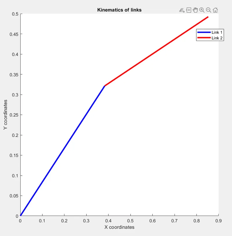
Line function is used to plot the coordinates x and y of links 1 & 2 for which two different colors are defined for better differentiation of Link L1 and L2. Link L1 is displayed in Blue and Link L2 is displayed in Red.
MATLAB Code with comments:
close all
clear all
clc

%Forward kinematics of a 2R robotic manipulator
%Inputs
length1=0.5;
length2=0.5;
theta1=40;
theta2=20;

%coordinates
x0=0;
y0=0;
x1=length1*cosd(theta1);
y1=length1*sind(theta1);
x2=x1+length2*cosd(theta2);
y2=y1+length2*sind(theta2);

%plotting
%for first link
line([x0 x1],[y0 y1],'linewidth',3,'color','b')
%for second link
line([x1 x2],[y1 y2],'linewidth',3,'color','r')
title('Kinematics of links')
legend('Link 1','Link 2')
xlabel ('X coordinates')
ylabel ('Y coordinates')
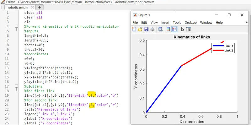
Plot output obtained from MATLAB program 1:
Conclusion for Program1:
Required x (x0, x1 and x2) coordinates and y (y0, y1 and y2) coordinates were obtained for single values of theta 1 and theta 2 by calculating the position of Link L1 and Link L2 using the solution set as follows.
Solution Set: [x0,y0],[x1,y1],[x2,y2]
Errors Obtained while executing the Program 1:
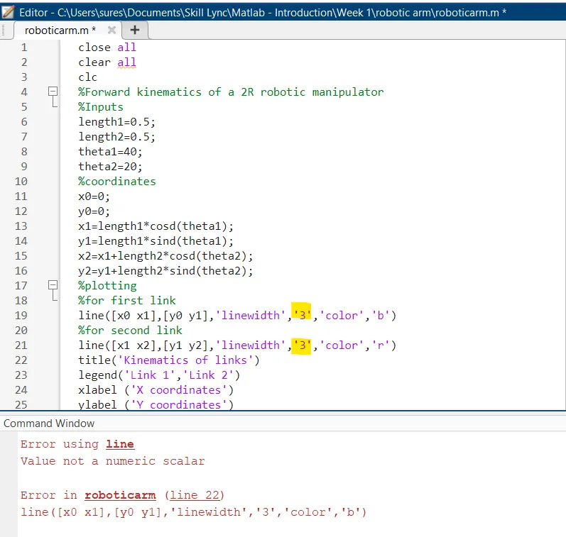
Error 1 (Program1): Typo Error while plotting the line command. I forgot that i was entering numeric value '3' while providing the linewidth. I was just including the ' ' without realizing what the requirement was from that command.
Rectification step: Removed the ' ' inside the numeric value 3 to produce the linewidth i required.
Program 2: To understand the working mechanism of the links L1 and L2 of the 2R robotic arm and to animate the rotational tendency of link L1 & L2 with various angles of Theta1 and Theta2.
Code Description:
Inputs given:
- Length of the link 1=0.5 m
- Length of the link 2=0.5 m
- Theta of the link 1= multiple values between 0 and 90 degrees.
- Theta of the link 2= multiple values between 0 and 90 degreess.
In previous program, we changed theta1 and 2 manually. Let us now use the "for loop" to consider theta1 and 2 multiple values. Secondary " for loop " is created to process and understand the difference in theta1 and theta2 for link 1 & 2.
Coordinates description:
From the representation of the robotic arm and from the geometry of the figure, we can represent the x0, y0, x1, y1, x2 and y2 as follows:
- x0 and y0 is the starting point of the Link L1.
- x1 and y1 is the end point of the Link L1 but it is also the starting point of the Link L2.
- x2 and y2 is the end manipulator coordinates.
MATLAB Code:
%To animate and create AVI file for robotic arm
clear all
close all
clc

%Inputs
length1=0.5;
length2=0.5;
theta1=linspace(0,90,10);
theta2=linspace(0,90,10);
ct=1

%for loop to understand the difference in theta1 & theta2 for links 1 & 2
for i=1:length(theta1)
    THETA1=theta1(i);
    for j=1:length(theta2)
        THETA2=theta2(j);

        %Giving Coordinates
        x0=0;
        y0=0;
        x1=length1*cosd(THETA1);
        y1=length1*sind(THETA1);
        x2=x1+length2*cosd(THETA2);
        y2=y1+length2*sind(THETA2);

        %Plotting
        plot([x0 x1],[y0 y1],[x1 x2],[y1 y2],'linewidth',3)
        title('Kinematics of links 1 & 2')
        axis([-0.1 1.5 0 1.5])
        legend('Link1','Link2')
        xlabel('x coordinate')
        ylabel('y coordinate')
        pause(0.03)

        %To create a movie
        M(ct)=getframe(gcf);
        ct=ct+1;
    end
end
movie(M)
videofile=VideoWriter('Forward_Kinematics.avi','Uncompressed AVI');
%To open, write and close the movie file
open(videofile)
writeVideo(videofile,M)
close(videofile)
Animation AVI File:
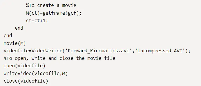
The above part of the MATLAB code provides the AVI file for the input and coordinate variables given to define the link with respect to different angles.
VideoWriter command is a MATLAB function used to create a movie and to observe the animation.
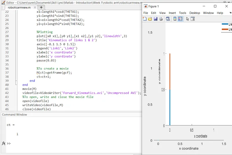
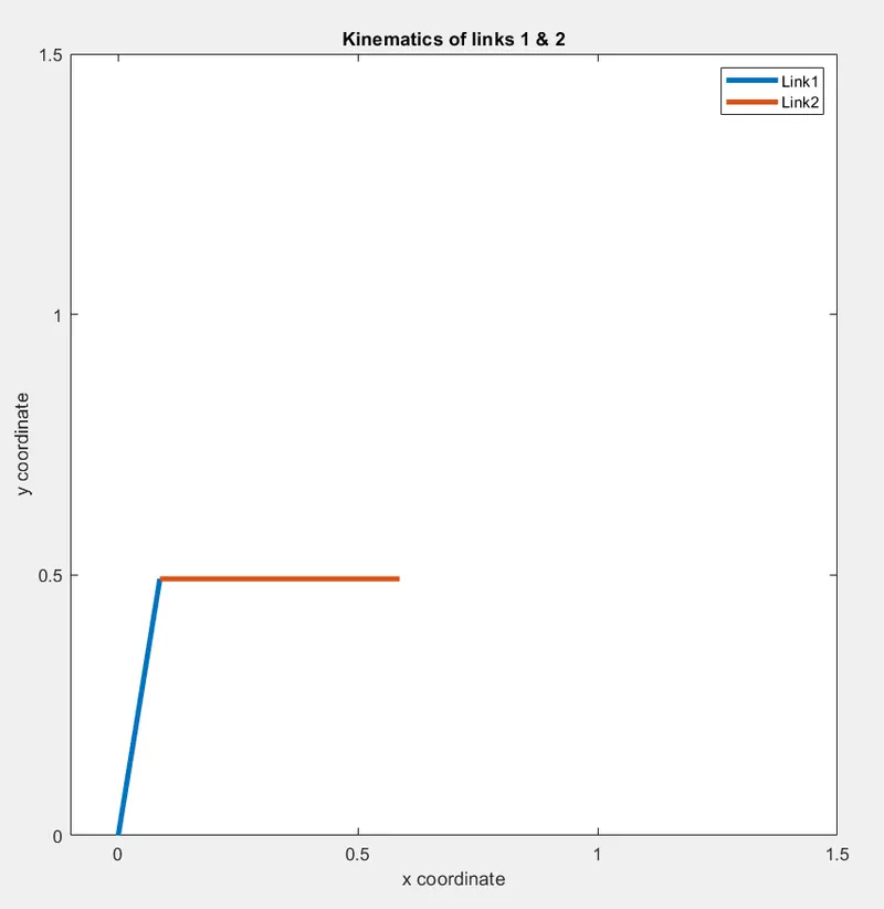
Plot Output (Note that the attached image is a screenshot taken when the animation video was playing due to which this image should be used as a reference only to represent that the required plot was produced successfully after running the command)
Google Drive link to animation AVI file:
https://drive.google.com/file/d/1rrTUIdf6xj8Uqer_l1YYrOvUOfxLJ6TZ/view?usp=sharing
Conclusion for Program 2:
The graph were plotted based on the multiple values provided for theta 1 and theta 2 using the linspace command. Since multiple values were given as Input to understand the kinematics of robotic arm, for loop was used to execute the program repeatedly. For every angle theta 1 and 2, the links L1 and L2 keeps changing it's X and Y coordinates.
Errors Obtained while executing the Program 2:
Error 1: Typo Error with the capitalization of THETA1 and THETA2. Due to this error, the variable was unrecognized since it was not previously defined anywhere in the editor window.
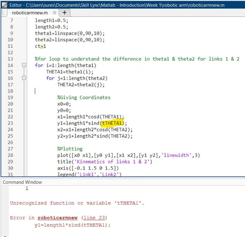
Rectification: I rectified the above error by deleting the t from tTHETE1.
Error 2: Unrecognized function 'M' in Movie function.
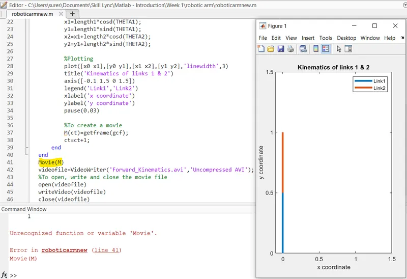
Rectification: To rectify the above error, I carefully observed the program and realized that the variable M was missing from the writeVideo(videofile,M) command. But even after rectification of this, there was still the same error being displayed after running the program.
Error 3: Unrecognized function 'M' in Movie function even after including M in the writeVideo command.
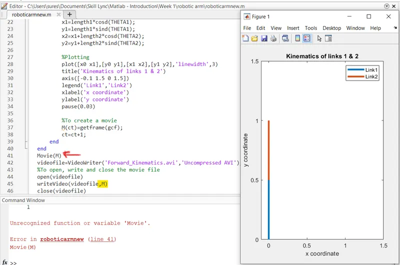
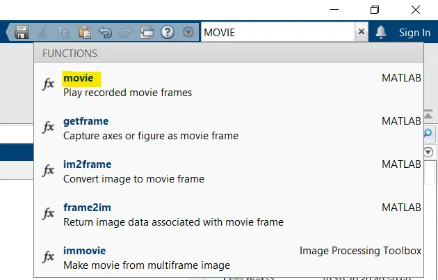
Rectification: I checked for the format to be included in order to play recorded movie frames using the search command option in MATLAB. Later, I realized that small letter alphabet m should have been used to play the movie frames recorded. MATLAB help center documentation helped me to correct the error and get the exact format required to successfully execute the program.
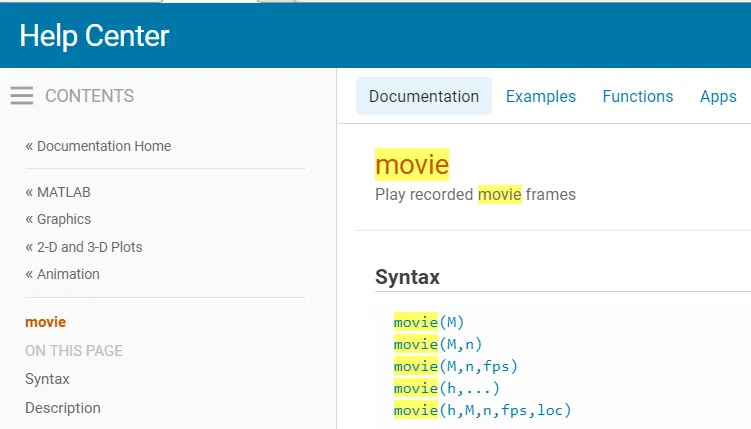
Rectified Output: Below program displays image to show the rectified error with plots obtained as per the command generated.