Week -2
AIM : Making a Simulink model of Doorbell using solenoid block .
OBJECTIVE :
- To make simulink model of doorbell using solenoid block assuming remaing parameters.
- Create a situation where the switch is closed for 2 seconds and then released.
- Observe the physical movement of the plunger.
GOVERNING EQUATION :
The bell uses a solenoid to generate the noise. Solenoid is an electromagnet with wire winding and a small metal piston inside it. The piston is attached to a spring assembly inside the wire winding. When electric current flows through the wire,electromagnetic field is generated which pulls the metal piston towards it.
BODY :
Block diagram of doorbell -
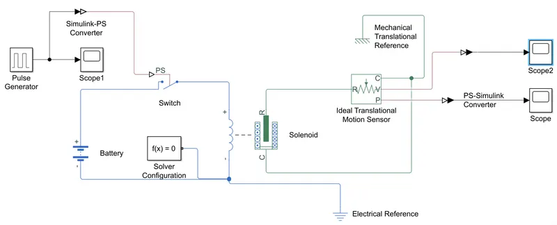
Explanation of block diagram used in model:
- pulse generator
- simulink-ps converter
- switch
- battery
- solenoid
- ideal translational motion senser
- mechanical translational reference
- electrical reference
- scope
- ps-simulink converter
- solver configuration
- Pulse generator is basically used to fed the input values to the model and one scope is connected to it so that we can see the input fedded is correct or not according to condition.
- Battery is used to give current source to the circuit as soon as the ps switch gets closed.
- ps switch is used which is connected to the pulse generator through simulink ps converter as our ps switch is simscape model as per the given input to the pulse generator ,ps switch will close the circuit at every 2 sec and again it will open the circuit .
- solver configuration is used to solve the model.
- solenoid is used to convert the electric signals to mechanical output of the plunger .
- Ideal transmittion motion senser is used to sense the movement of plunger.
- scope is joined with Ideal transmittion motion senser to plot the output of plunger movement.
OUTPUT:
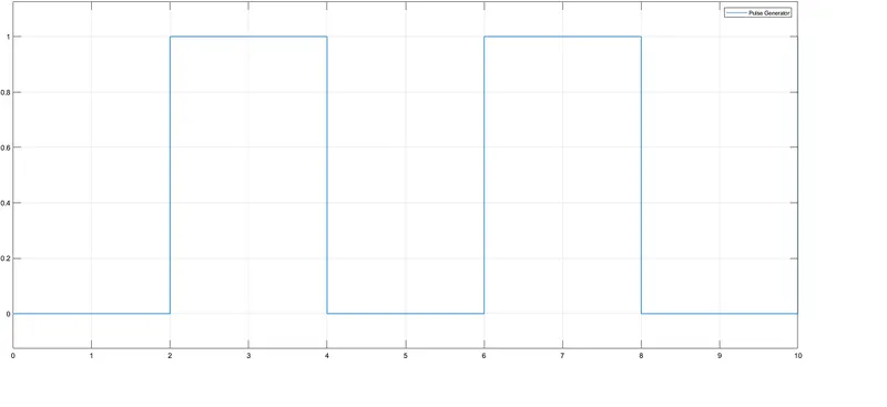
From above graph we can observe that , at every 2 sec switch is closed and after 2 sec switch is closed.
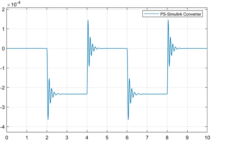
From the above plot we can see that there are vibration at every 2 sec which means that there is the movement of plunger at every 2 sec.
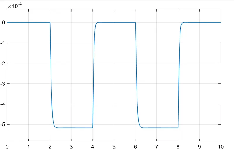
Now if we change the mechanical parameter of solenoid we can see smother graph ,which shows the displacement of plunger .
Here we have decerese the stifness value from 200 to 100. and value of damping coefficient to 5 for smother displacement output.
AIM :Use a thermistor to sense the temperature of a heater & turn on or turn off the fan as per the given conditions.
OBJECTIVE :
- To create simulink model which sense the temperature of heater and turn on or off the fan as per given conditions .
- Given conditions are as follow -
- Temperature source: 20 °C from 0 to 10 seconds, 27 °C from 10 to 30 seconds, 23 °C from 30 to 50 seconds
- Fan conditions: ON if the temperature above 25 °C, OFF otherwise.
GOVERNING EQUATION :
A thermistor is a resistance thermometer ,or a resistor whose resistance is dependent on temperature .
Thermistor are of two opposite fundamental types :
1 . With NTC thermistor , resistance decreases as temperature rises . An NTC is commonly used as a temperature sensor, or in series with a circuit as an current limiter.
2 . With PTC thermistor , resistance increases as temperature rises . PTC thermistor are commonly installed in series with a circuit , and used to protect against overcurrent condition , as resettable fuse.
Block Diagram -
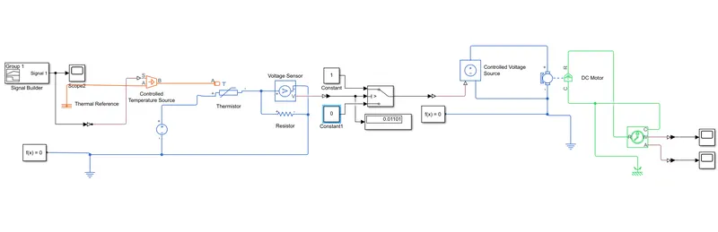
Block used in this model:
- signal builder
- controlled temperature source
- Thermistor
- Controlled voltage source
- DC motor
- ideal rotational motion sensor
- display
- scope
- elctric source
- solver configuration
- constant
Explanation :
Initially we have to create the model for the reference temperature which is 25 degree temperature celcius and get the corrosponding voltage value which is consider as a threshold value for the futher model .
The constant value is 298.15k which is the reference temperature and it is connected to the controlled temperature block using simulink ps converter . In simlink PS converter we assume as a first order approximation , that the relationship between resistance and temperature is linear . Controlled temperature block represents an ideal energy source in a thermal network that can maintain a controlled temperature difference regardless of the heat flow rate . The temperature difference is set by the physical signal port s . A positive temperature difference causes the temperature at port B to be greater than the temperature at port A . port A is connected to the thermal reference and controlled temperature block is further connected to the Negative thermal coefficient NTC thermistor . Resistor and voltage sensor is connected in series and output of voltage sensor is obtained in display on running the simscape block and the value obtained is the threshold valve which is further used in modelling.
Temperature source signal builder is provided by signal builder which create and generate interchangable signals whose waveforms are piecewise linear as shown bwelow ,
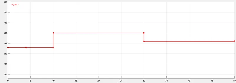
Output from signal builder :
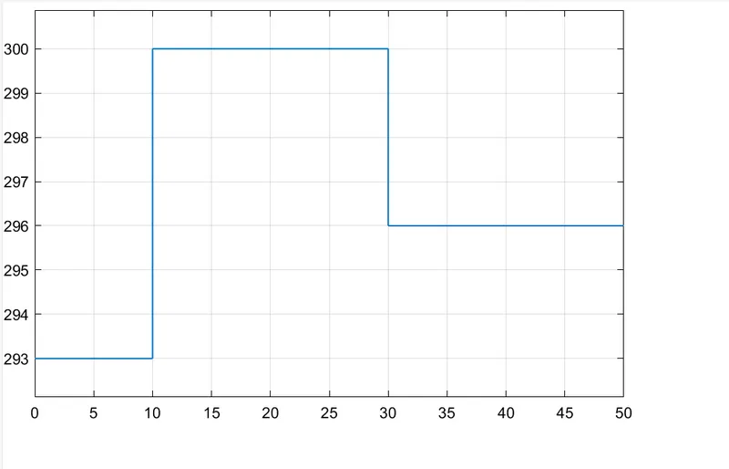
Out put from the voltage sensor is connected to the switch through simulink ps converter in switch block parameter threshold value has to entered which is obtaioned previously . The first and third input ports are data ports ,and the second input port is the control port . Constant block 1 and 0 for switch on and off condition respectively . When the condition is satisfied in control port then signal flow through the constant 1 block otherwise constant 0 block.
output from switch is connected to the controlled voltage source block which supplies voltages to the DC motor which is the replica of fan and further DC motor is connected to the ideal rotational motion sensor which sense the angular motion of DC motor/fan and records it in scope as output. In this two solver configuration block is used because the first solver configuration is intruppeted by simulink ps converter .
OUTPUT:
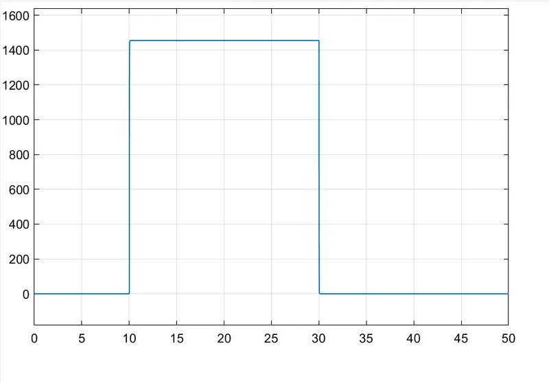
The switch is connected to the controlled voltage source block which supplies voltages to the DC motor which is the replica of fan and further DC motor is connected to the ideal rotational motion sensor which sense the angular motion of DC motor/fan and records it in scope as output. In this two solver configuration block is used because the first solver configuration is intruppeted by simulink ps converter .
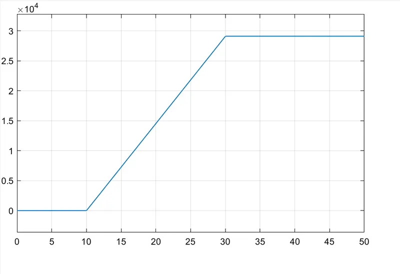
Below graph shows the output in scope-
CONCLUSION :
- From the plot initially from 0-10 sec the plot is linear because the temperature value is 293k which is less than reference value hence the fan is in off condition.
- In the time period from 10-30 sec the variation is observed because the temperature value is 300k which is greater than the reference value hence the fan is in on condition .
- In the time period from 30-50 sec the plot is linear and corresponding temperature is 296k which is less than the reference value hence fan will be in off condition .