Week -2
Q1: To make a simulink model of doorbell using a solenodial block.
Obj:
- To create a simulink block of a doorbell
- To create a situation where the switch is closed for 2 seconds and released.
- Plunger position should be observed.
Diagram given:
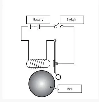
-The core of the convectional bell is electromagnetic, which is basically a coil is wrapped around a piece of metal. when the current passes thorugh it creates magnetic field.
-When the circuit is closed the current flows, the more the coil larger the field is produced. this field disturbs and make the movement of the arm.
-Word Solenoid is used in engineering to describe the complete setup which includes an electromagnet and an actuator that transfer electrical energy to mechanical energy.
Blocks used:
- Pulse Generator
- Scope
- Switch
- Battery
- Solenoid
- Electrical Referance
- Solver Configuration
- Simulink-PS converter
- PS-Simulink converter
- Mechanical Translation referance
- Ideal translational motion sensor
Explination:
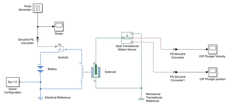
- To create a doorbell model in Simulink first.
- The process starts with a Pulse Generator, which provides an input to the system based on a given condition which is 2 seconds delay. Here we have used a pulse width of 50% to get a much wider output waveform.
- Pulse Generator is connected to a Simulink-PS converter which converts the signals to a physical signal.
- Simulink-PS converter is connected to an electrical element based Switch which is further connected to a Battery & a Solenoid block.
- We have placed an Electrical Reference port (for electrical ground) along with a Solver Configuration which defines solver
settings to use for simulation. Solenoid is connected to an Ideal Translational Motion Sensor in which the physical signal ports V and P report the velocity and position respectively. The R & C port is connected to the R & C port of the solenoid.
- The signals from port V & P, the motion sensor is converted to a Simulink signal using a PS-Simulink converter. Output velocity and movement of the plunger (position) can be seen through their respective Scope plots.
- In general blue lines represents the Electrical System whereas the Green lines represent the Mechanical System.
Result:
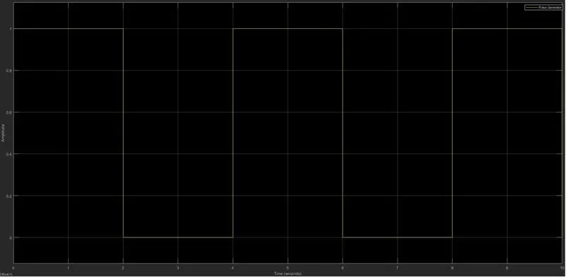
Inupt Scope:
The time-based pulse is generated for every 2 seconds based on its cycle period which is of 4 seconds.
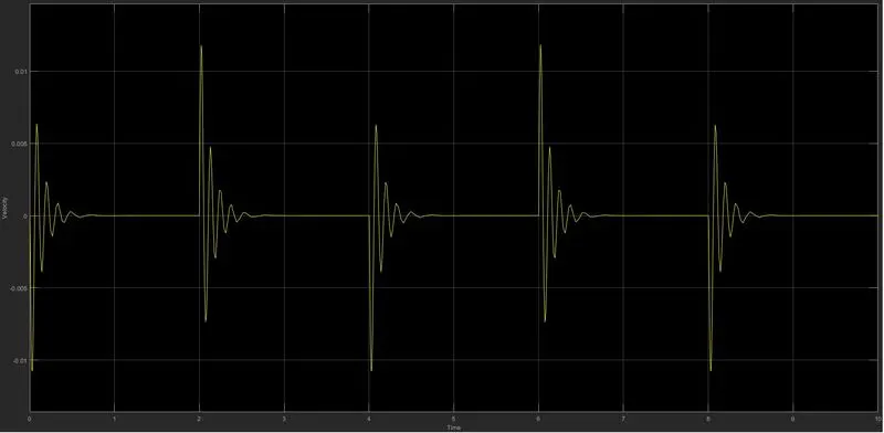
Output Scope 1 - Velocity of the Plunger
The time-based pulse is generated for every 2 seconds based on its cycle period which is of 4 seconds. Hence we can see some disturbances every 2 seconds.
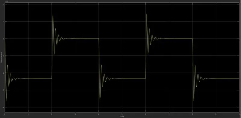
Output Scope 2 - Displacement of the Plunger
The time-based pulse is generated for every 2 seconds based on its cycle period which is of 4 seconds. Hence we can observe the change in the physical movement of the plunger.
Result:
From the above results, we have arranged the switch which receives electrical power from the battery and pulls the metal arm to hit the bell producing sound. Also, have figured out the velocity and position of the plunger for a given situation where the switch is closed for 2 seconds with the help of plots.
Q2. Use a thermistor to sense the temperature of a heater & turn on or turn off the fan as per the below conditions
Given
Temperature source: 20 °C from 0 to 10 seconds, 27 °C from 10 to 30 seconds, 23 °C from 30 to 50 seconds
Fan conditions: ON if the temperature above 25 °C, OFF otherwise.
Hence Time (sec) Temperature (°C) ON / OFF
0-10(sec) 20°C OFF
10-30(sec) 27°C ON
30-50(sec) 23°C OFF
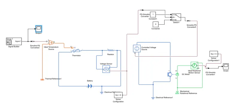
A fererance image of block diagram is given below.
Explination:
-We have used a Signal Builder and temperature ranging as 20°C, 27°C & 23°C. The results can be seen through its connected Scope (Temperature °C). These signals are converted using a Simulink-PS converter and then it passed through Thermal Blocks which has a Controlled Temperature Source which represents an ideal energy source in a thermal network that can maintain a controlled temperature difference regardless of the heat flow rate where the temperature is equal to absolute zero.
-Electrical Blocks consist of Battery, Voltage Sensor and Resistor. Here the Electrical Reference port (for electrical ground) along with a Solver Configuration which defines solver settings to use for simulation.
-The output signals from the voltage sens are converted using PS-Simulink converters. The first converter helps to get the Voltage Drop and the second converter is further connected to a Switch having two constant inputs 0 & 1 named as OFF & ON respectively.
-To get the desired result we need to give some threshold value to the switch. In our condition, the Threshold value is 0.01196. then the output from the switch is connected to a Display and the Scope represents OFF & ON conditions. In this circuit, a battery, another Current sensor (Ammeter) and a Universal Motor are connected to the switch mentioned
previously.
-The C & R ports of the Universal Motor are connected to an Ideal Rotational Motion Sensor to measure the angular velocity of the fan in the motor. The physical signal port 'W' is used to measure the angular velocity of the fan by connecting a Scope.
-when circuit is closed and current flows, the universal motor rotated and it produces a positive torque acting from the mechanical ports C to R.
Output 1- Voltage Sensor Waveform: (xaxis time) (yaxis Temperature)
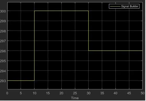
Here, the voltage is higher between the time 10-30 seconds at which the temperature is reaching 300K, so the voltage drop across the resistor will also be high. The thermistor's main work here is to sense the temperature and then
drive the fan system accordingly.
Output 2- angular velocity with respective to time
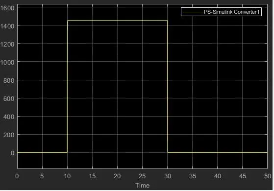
So our two objectives are successfully achieved for both the problem statements.