Week -2
1. OBJECTIVE : Make a simulink model of doorbell with using solinoid
Block diagram :
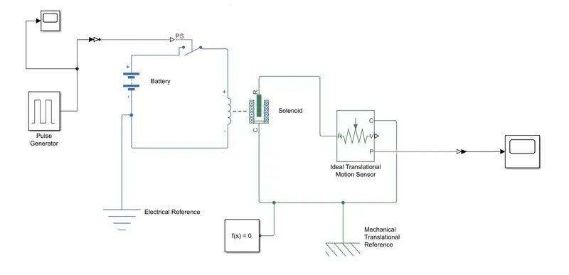
Explanation :
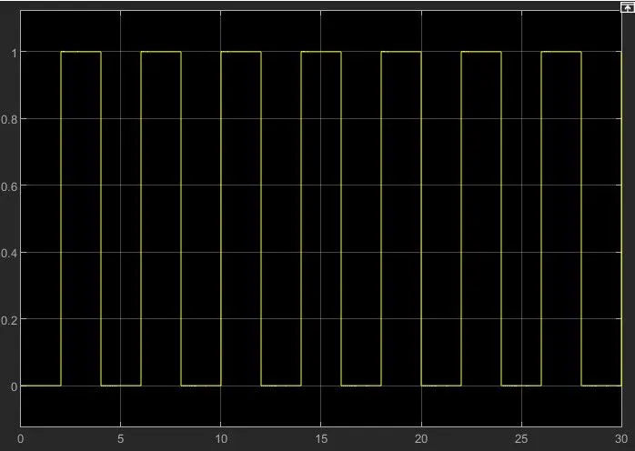
1. Pulse generator :Pulse generator is used to provide square wave signal to the switch to satisfy the condtion.
As per the condition, Switch is closed for 2 seconds and then released.
2. Simulink-PS converter is used to convert simulink sugnal into physical signal.
3. Switch is controlled by an external physical signal.
4. Battery is used to give power to the closed loop.
5. Solinoid block is to convert the electrical energy into mechanical energy. Used as per the question to hold the plunger when switch is closed and released the plunger when switch is open.
6. Ideal Translation Motion sensor is used to sense the movement of the plunger and giving output to the scope.
7. PS- simulink converter is used to convert the physical signal into the simulink signal.
8. Scope is used to show the result of plunger movement to the observer in the graph.
9. Solver configuration is used to specifies the solver parameters that model need before the simulation.
10. Mechanical Translation references is usedd as referance connection for mechanical translational parts.
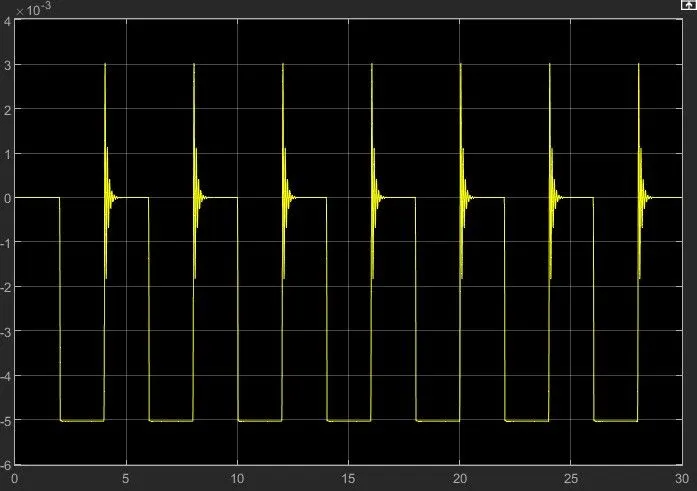
Result :
Conclusion of Door bell :
Giving input as time period for 2sec in the pulse generator to open and close the switch. When the switch is closed the solenoid block recieves electrical power from the battery and plunger moves from part R to port c to hit the bell and produce sound.
Physical movement of the plunger is observed by using translational motion sensor and physical output is oonverted into simulink output model and is displayed in the scope. By reducing the spring constant value and increasing the damping value, vibrations will be reduced.
2. OBJECTIVE : Use the thermister to sense the temparature of a heater & turn on or turn off the fan.
simulink model :
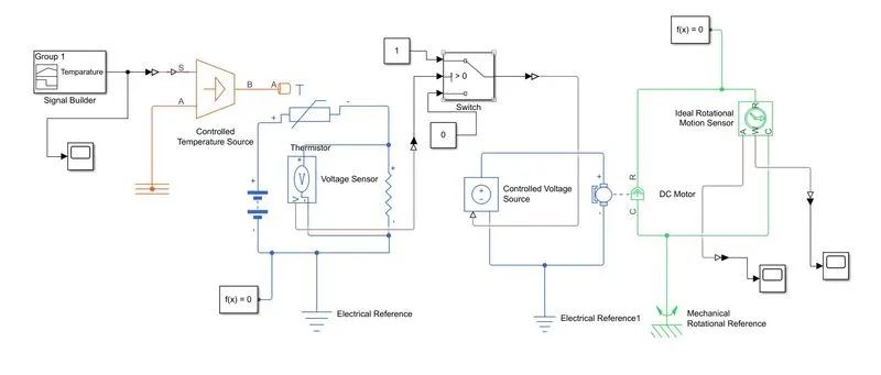
Explanation :
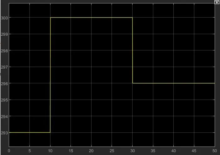
- As per the given condition for time and temparature, gives the value to the signal builder and configure as per our condition.
- There is a simulink-PS converter that converts simulink signal to physical signals.
- Give this signal to the controlled temparature source block which represents the ideal source of thermal energy that is powerfull enough to maintain specified temparature difference across the source regardless of the heat flow consumed by the system.
- This signal then passes to Thermistor which connected to the battery.
- The voltage sensor is connected to a resistor which is used to measure the voltage as a threshold value for the condition of our circuit.
- As per fan condition that ON if the temparature above 25 degree, OFF otherwise.we uses the switch and provide a threshold value.
- If the signal value is greater than the threshold value then turn it ON otherwise it will be turned OFF.
Results :
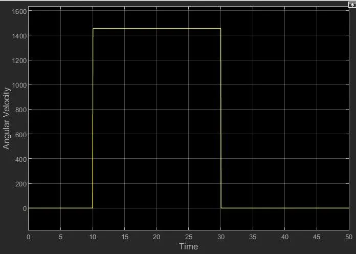
Angular Velocity :
Angular Dispacement :
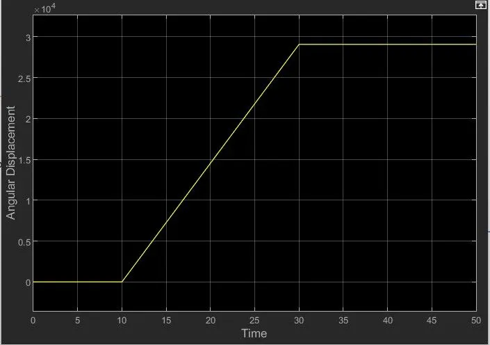
From 0-10 sec the fan is OFF because the temparature is 293k which is below 298k, after 10 sec it goes to 300k, so the fan will turn ON because the temparature exceeds 298k. After 30 sec the fan will turn OFF because the temparature goes to 293k which is less than 298k.