Week -2
- Make a Simulink model of Doorbell using solenoid block with the following details:
simulink and simscape blocks used:
1.Pluse generator
2.Switch
3.battery
4.ps to simulink converter
5.solenoid
6.mechanical transtional referance
7.electrical reference
8.ideal transtional motion sensor
9.scope
10.simulink to ps converter
block model
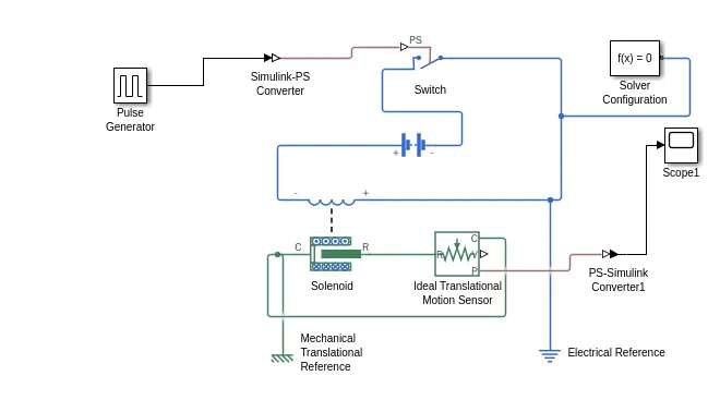
condition: the switch is to closed for 2sec and then released.
Explanation:
The pulse generator is used to produce square wave pulses as input in regural intervals.switch block is used for opening and closing operations.simuink to ps converter is used to convert the simulink input to simpscape model.battery is given for power supply to the solenoid block.Ideal transational motion sensor is used to sense the electrical input signal.scope is used for graphical representation.
firstly,the pulse generator is conncted to the simulink to ps converter and then connected to switch.switch block is controlled by external physical signal and the external physical signal greater the switch closed or else switch is open.a battery is connected to the switch.the positive terminal of the battery is connected to the negative terminal of a solenoid.The positive terminal of solenoid is connected to the negative terminal of switch.an electrical reference is connected to the whole electrical circuit.
The port C is connected to the mechanical reference.the port R of solenoid is connected to the R port of ideal transational motion sensor.the port P is connected to PS-simulink converter and then thes connected to the sope for output.
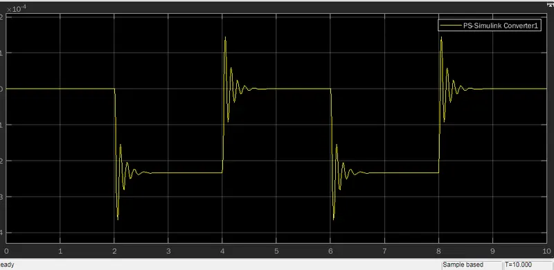
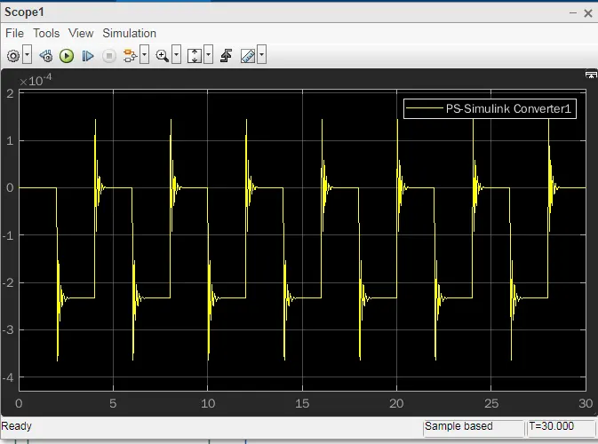
Giving the input to the pulse generator as 2sec the switch tends open and close.when the switch is closed the solenoid blocks recieves the electrical power from the battery and plunger moves from port R to port C to hit the bell to produce sound.physical movement of the system is sensed by ideal transational motion sensor and the output is displayed in scope.
output:
2. Use a thermistor to sense the temperature of a heater & turn on or turn off the fan as per the below conditions:
condition:
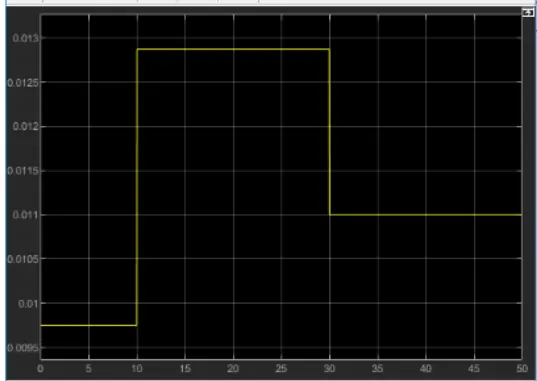
Temperature source: 20 °C from 0 to 10 seconds, 27 °C from 10 to 30 seconds, 23 °C from 30 to 50 seconds
Fan conditions: ON if the temperature above 25 °C, OFF otherwise.
Blocks used:
signal builder:the signal builder blocks creates interchangeble groups of piecewise linear signal source.
controlled temprature source:The block represents an ideal source of thermal energy.
thermistor:It is a type of resistor whose resistancs depends upon temprature.
voltage sensor:these device sense the voltage beteween the electrical circuit.
electrical reference:IT represents the electrical ground.
block diagram
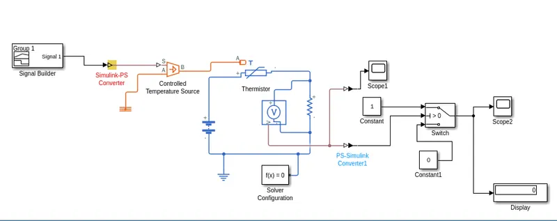
In this model the input is given the signal bulider as temprature.the simulink to ps converter used to conncet to the controlled temprature source.port A connected to the thermal reference and port B connected to the thermistor.the positive of thermistor connceted to the positive battery source and negative connected to the resistor to create an electrical circuit.A voltage sensor is connected across the resistor to sense the voltage.A solver function is provided.the switch connectd across the electrical input witn constant and scope is connected to display the output.