Week -2
AIM:
- To make a Simulink model of doorbell using solenoid block.
- To make a Simulink model of a thermistor, sense the heater's temperature and turn on or turn off the fan as per the temperature conditions.
PART-1 (DOORBELL USING SOLENOID)
The solenoid is an electromagnet. A magnetic field is generated by passing a current through the conducting wires, attracting magnetic materials. This phenomenon is used in the bell. When the bell switch is pressed, the current passes through the circuit, existing the electromagnet and pulling the plunger towards the metal portion. This produces a ringing sound.
SIMULINK MODEL:
Blocks used in the model:
- Pulse Generator
- Switch
- Battery
- Solenoid
- Ideal Translational Motion Sensor
- Mechanical Translational Reference
- Electrical Reference
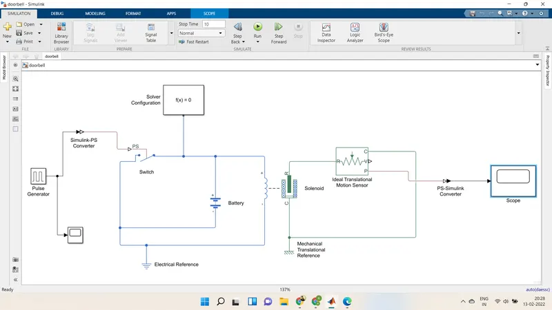
Model Explanation:
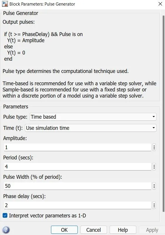
A pulse generator is given as input with the following specifications. The condition was that the bell was engaged for 2 s and then released. The same was implemented by providing 4 seconds and pulse width as 50% of 4 seconds, i.e., 2 seconds. Phase delay was given as 2 seconds, so the simulation starts from the unengaged condition of the switch.
Block parameters of Pulse Generator:
The signal from the pulse generator was converted using a Simulink-PS converter and is given as the input to the switch. A Solenoid is introduced, and a battery is connected to it. The voltage of the battery connection was made the same as that of the rated voltage of the solenoid. The Switch is also connected to the same circuit. The position of the solenoid plunger is measured using an ideal translational motion sensor connected to the course. The initial work was set to 5mm in the translational motion sensor. Both mechanical and electrical references were related to the respective circuits. The output from the ideal translational motion sensor is converted using a PS-Simulink converter and is given to the scope to display the results. The area was also connected to the input to visualize its behavior. The solenoid block's spring constant and damping parameters were altered to obtain the desired graph.
RESULT:
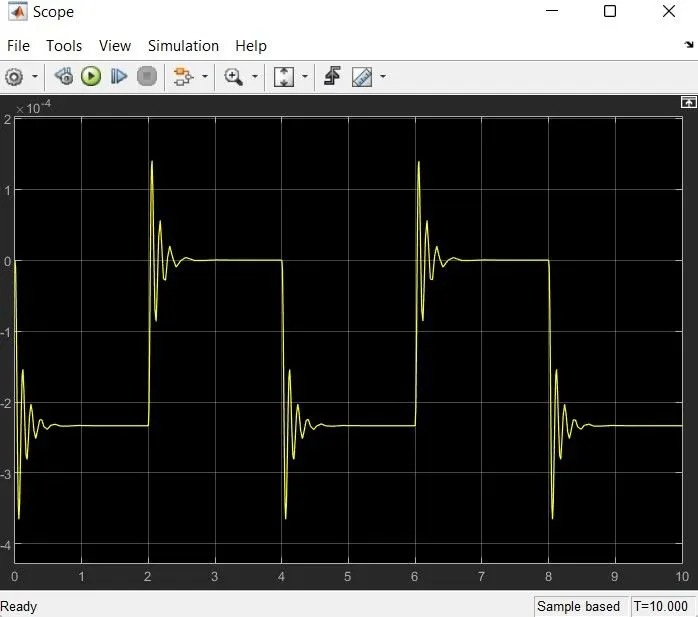
RESULT:
- This is the result obtained for 10 seconds of the given simulation.
- For every 2 seconds, the switch is turned on and off; hence such waveform is obtained.
- The damping effect is observed because of the damping parameter set in a solenoid block of 1N/(m/s).
- The curve is positive as motion direction is set as 'Port R moves away from port C.
PART-2 (USE A THERMISTOR TO SENSE THE TEMPERATURE OF A HEATER & TURN ON OR TURN OFF THE FAN AS PER THE BELOW CONDITIONS)
THEORY:
A thermistor (Thermal resistor) is a resistor whose electrical resistance varies with temperature changes. Although all resistors' resistance will fluctuate slightly, a thermistor is particularly sensitive to temperature changes.
BLOCKS USED:
- Signal builder
- Controlled Temperature source
- Thermal Reference
- Thermistor
- Voltage Sensor
- Resistor
- Battery
- Electrical Reference
- Switch
- Simulink-Ps converter
- Ps-Simulink converter
- Scope
- Display
Simulink Model: 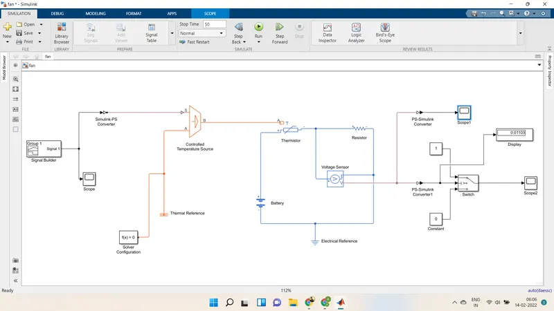
This figure shows the representation of a thermistor connection that senses the temperature of a heater and passes the signal to a switch where a threshold limit is already set. If the temperature is above or equal to the threshold limit, it gives "1" as output, "Switch On." If the temperature is below the threshold limit, it will show "O" as output which means "Switch Off." The input signal is generated with the help of a "Signal Builder" block. This signal is created according to the conditions given in this challenge. The requirements are as follows:
Temperature source:
- 20 °C from 0 to 10 seconds
- 27 °C from 10 to 30 seconds
- 23 °C from 30 to 50 seconds
Fan conditions: ON if the temperature is above 25 °C, OFF otherwise.
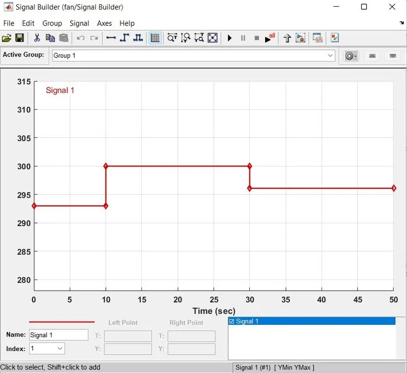
The temperature is converted in Kelvin from degree Celcius because the signal converter does not take the "C value as input. I also have to set the signal unit as "Kelvin in Simulink-PS Converter.
The formula for conversion: 1°C-273.15 K
The input signal on Signal Builder Block:
From 0-10 sec- Temperature is 293.15 K
From 10-30 sec- Temperature is 300.15 K
From 30-50 sec- Temperature is 296.15 K
MODEL EXPLANATION:
- At first, the signal is created in "Signal Builder" and further passes to "Simulink-PS Converter" to convert the input signal into the physical movement.
- This physical signal is connected to the "Controlled Temperature Source" block. This block is connected to the thermistor and a "Thermal Reference" block.
- The thermistor is a part of an electric circuit where a battery, a voltage sensor, a resistor connected parallel to the voltage sensor, an electrical reference are bound to make a complete circuit. A solver configuration is related to that electrical circuit to solve all parameters before the beginning of the simulation.
- The voltage sensor senses the temperature in voltage and sends the data to its port "V."
- From this port, we get our output and send it to two different "PS-Simulink Converter."
- The signal is sent to the threshold switch from the converter. In the switch, the threshold limit is set to 0.01099. If the temperature is above or equal to the threshold limit, it gives "1" as output, "Switch On." If the temperature is below the threshold limit, it will show "O" as output which means "Switch Off." The input signal is generated with the help of a "Signal Builder" block.
- The switch is connected to the scope to see our output plot.
- From converter-1, it converts the physical signal into a Simulink signal and sends the voltage data from the Voltage Sensor to display. This display gives us the threshold value of voltage. This value is set in the switch.
RESULT:
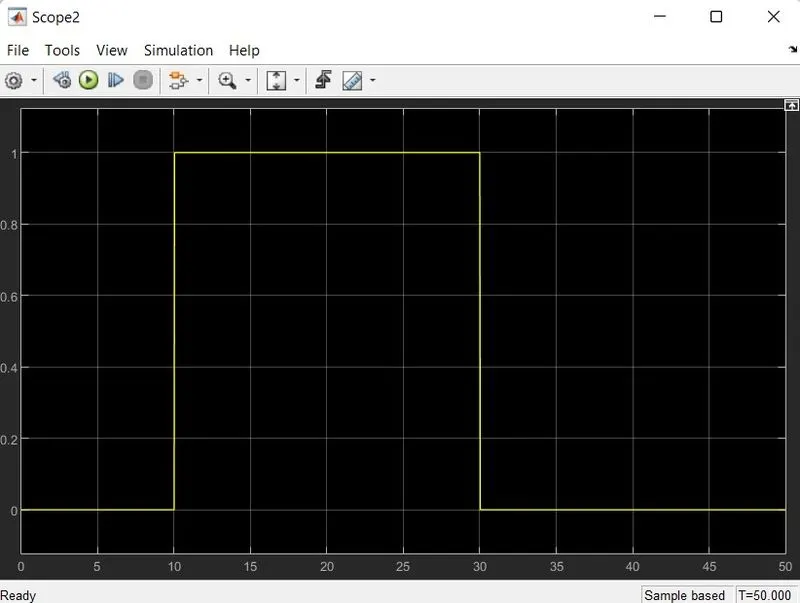
Hence, the plot clearly shows the fan is on when the temperature is above 25C (10sec - 30sec), and it is off otherwise.
CONCLUSION:
-
In the first part, we used a solenoid to convert the electric energy into mechanical energy and made a Simulink model simulate the Doorbell; here, we can conclude that the plunger is moving from its initial position of 5mm with a time delay of 2sec; this time delay happens while the plunger is suddenly disconnecting from the bell and moving away.
-
In the second model, we use Thermister to sense the temperature, and according to our condition, we put the threshold value to the switch block to turn on and turn off the fan at a particular temperature.