Week -2
1. AIM: To Make a Simulink model of Doorbell using solenoid block with the following details:
In the above arrangement, when the switch is closed the electromagnet receives electrical power from the battery and pulls the metal arm to hit the bell producing sound.
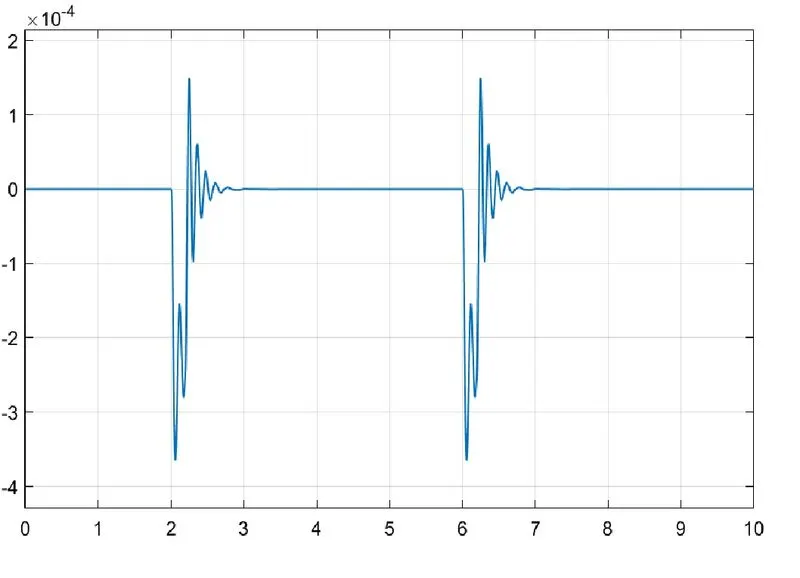
Creating a situation where the switch is closed for 2 seconds and then released & Observing the physical movement of the plunger.
SIMULINK MODEL:
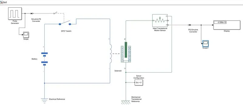
EXPLANATION:
The entire simulink model is made by using individual blocks such as PS & SP simulink converters, Pulse generator, electrical and mechanical references, solenoid, battery, SPST switch, solver and an ideal translational motion sensor.
The construction of the model was done following the steps given below:
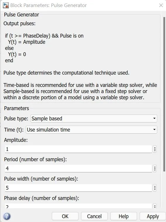
1. Create the pulse generator block and give assign suitable block parameters such as phase delay of 2 seconds and period for 4 seconds.
2. The pulse generator takes an analog signal as the input which needs to be converted into a signal which the simulink can comprehend. Thus a PS (Physical to Simulink) converter is used.
3. The pulse now has to be transferred to a switch connected to a battery and a solenoid.
4. Components like battery, solenoid and a switch are functionaries of an electrical circuit system, thus demanding an electrical reference attached to a solver configuration.
5. Due to the electromagnetic phenomenon of the solenoid, the piston or the iron core situated inside the solenoid is displaced by virtue of the current passed in the windings. Therefore, the electrical energy is converted into mechanical work.
6. This translation can be recorded by an ideal translational motion sensor attached to the solenoid. Here a mechanical reference with solver configuration must be added.
7. Lastly inorder for the user to comprehend the results the signal needs to be converted into a physical response using a SP simulink converter connected to the display block.
8. Scope Blocks are attached to the model wherever necessary.
The physical movement of the plunger can be understood from the graph recorded.
2. AIM: To Use a thermistor to sense the temperature of a heater & turn on or turn off the fan as per the below conditions:
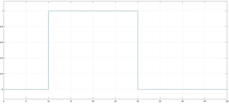
Temperature source: 20 °C from 0 to 10 seconds, 27 °C from 10 to 30 seconds, 23 °C from 30 to 50 seconds
Fan conditions: ON if the temperature above 25 °C, OFF otherwise.
SIMULINK MODEL:
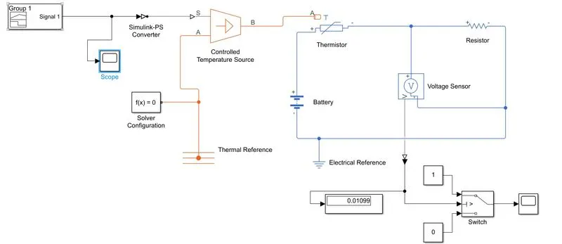
EXPLANATION:
The model is made by the use of simulink blocks such as - Signal builder, PS& SP converters, Thermal and electrical references, battery, thermistor, controlled temperature source, switch, display and solver configuration.
The construction of the model was done following the steps given below:
1. A signal builder block is created inorder to give the inputs according to the problem statement.
2. Within the signal builder we adjust the time frame to 50 seconds and temperatures ranging from 0 to 300 Kelvin.
3. The Temperature source conditions are set accordingly by adjusting the position of the various lines in the signal.
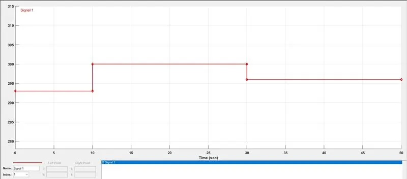
4. The analog signal as input needs to be converted into a signal which the simulink can comprehend. Thus a PS (Physical to Simulink) converter is used.
5. The Block parameters for Simulink PS converted are adjusted to a first order filtering.
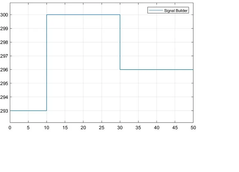
6. Blocks like controlled temperature source and thermistor are created and are attached to the input signal.
7. The temperature source is annexed to a temperature reference block with a solver configuration.
8. The thermistor records and can measure the temperature within a certain temperature limit.
9. The functioning of a thermistor is based on a battery source and the resistance.
10. The battery source, resistance and voltmeter are added into our model. The Voltage sensor is attached parallel to the resistor for recording the voltage.
11. This electrical ciruit is attached to an electrical reference representing earthing in the ciruit.
12. The voltage signal is then converted back into a physical response.
13. The output voltage is now connected to a switch block adjusted to a threshold value of 0.01099.
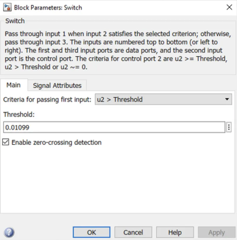
14. The other two ports of the switch are connected to constants 0 & 1. Thus, when the output (voltage) is more than the threshold the value it shows 1 (meaning the fan is ON) otherwise 0 (meaning the fan is OFF).
15. Scope Blocks are attached to the model wherever necessary.