Week -2
Question-1)
Aim:
To make a simulink model of a doorbell using solenoid block.
To use a thermistor to sense the temperature of a heater & turn on or turn off the fan.
1.Door Bell
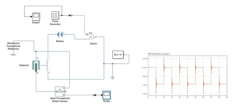
Simulink Model:
Simulink Model Explanation:
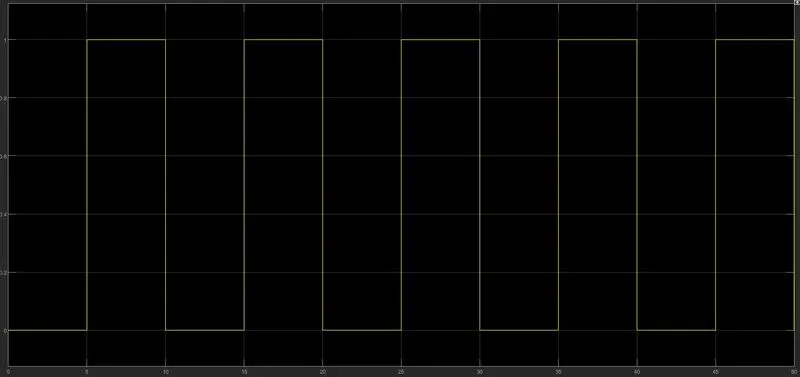
• The pulse generator is used to create square wave pulses at regular intervals. The block waveform parameters Amplitude, pulse width,period and phase delay,determine the shape of the output waveform.
• The switch block used is controlled by external physical signal.If the external signal is greater than the thresold parameter then the switch is closed, otherwise switch is open.
• The positive terminal of the switch is connected to switch and the negative terminal is connected to the electrical reference.
• The Solenoid block is connected with switch and battery and we will get a complete electrical circuit. The port c is connected with mechanical reference.
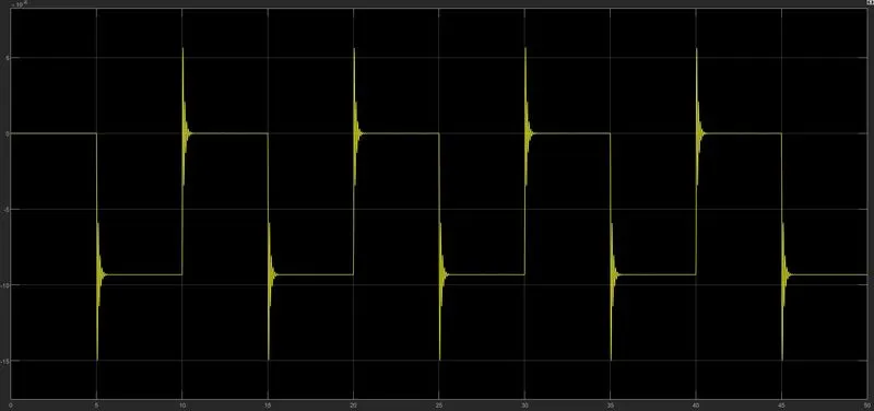
• The ideal translational sensor is connected with solenoid block R to observe the movement of the plunger.
Scope is connected with the ideal translational sensor to get the output.
• PS-Simulink converter is used to convert the physical signal to simulink signal.
• Solver Configuration:Each physical network represented by a connected simscape blocks requires solver setting information for simulation
Input & Output Pulse
Question-2)
AIM: 'To use a Thermistor to sense the Temperature of a heater & turn on or turn off the Fan!
OBJECTIVE:
• To create a model of Thermistor using simulink which will detect the temperature and gives the signal weather to turn on or off the fan.
Blocks used:
1. Signal Builder: This block is used to give our inputs of Temperature with time.
2. Controlled Temperature Source: This block represents an ideal energy source in a thermal network that can maintain a controlled temperature difference regardless of the heat flow rate.
3. Thermistor: This block represents an NTC thermistor using the B-parameter equation.
4. Resistor: A simple resistor block inserted into the circuit.
5. Voltage Sensor: The block represents an ideal voltage sensor, that is, a device that converts voltage measured between any electrical connections into a physical signal proportional to the voltage.
6. Switch: This block pass through input 1 when input 2 satisfies the selected criterion; otherwise, pass through input 3.
7. Controlled Voltage Source: This block represents an ideal voltage source that powerful enough to maintain the specified voltage at its output regardless of the current passing through it.
8. DC Motor: This block represents the electrical and torque characteristics of a DC motor.
9. Ideal Rotational Motion Sensor: This block is used to detect wether there is any rotational motion in the DC Motor during the simulation.
10.Scope Block
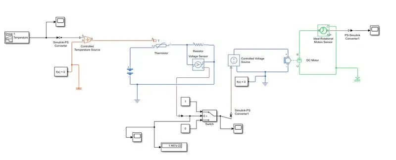
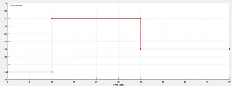
Note: For 25 Deg.C temperture the thresold voltage value used is-1.6e-22 at switch block for reference.
Output-
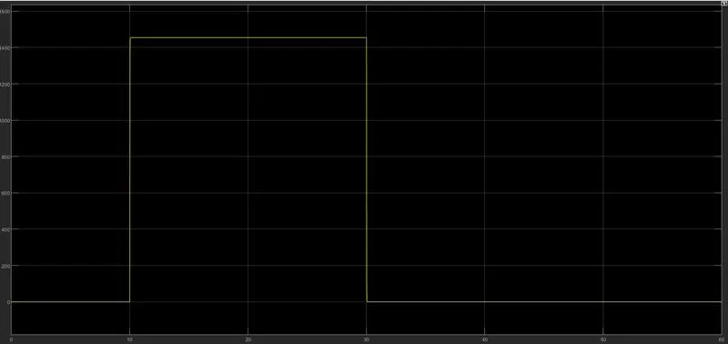
Observations:
• We can observe that there is a change in angular velocity from 10sec to 30sec during the simulation.
It interprets that, when the temperature value crosses the 25deg the motor is getting the power and rotating, thereby achieving the given task.
CONCLUSION:
• The Creation of Thermistor model to measure the Temperature is done using the Simulink model and the results are satisfactory.