Week -2
SIMULINK WEEK 2 CHALLENGE
1. Aim
This project is divided into two parts:
- To design a Simulink model of a doorbell, in which the switch is closed for 2 seconds and then released and to observe the physical movement of the plunger during the ON/OFF conditions.
- To design the model of an automatic temperature controlling system based on the given conditions.
2. Theory
The main component of the doorbell model is the solenoid. A solenoid is an electromagnetic device comprising a coil of wire, housing, and a moveable plunger or armature. When an electrical current is supplied, a magnetic field is created around the coil which can attract or deflect the plunger. It therefore converts electrical energy to mechanical work [1].
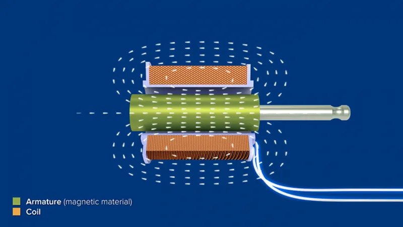
Figure 1 Solenoid
The coil is constructed from numerous turns of tightly wound copper wire. A strong magnetic field/flux is created when an electrical current flows through this wire. The housing surrounds the coil and concentrates the magnetic field produced by the coil. It is normally made of iron or steel. The plunger is drawn to the stop by the concentration of the magnetic field, which provides mechanical force to do work [1]. Solenoids have a wide range of applications – in inductors, valves, antennas, automotive components, etc.
The solenoid block in Simscape consists of two types of ports: two electrical and two mechanical ports each. The electrical ports comprise of the positive and negative terminals through which the electrical current flows to create the magnetic field. The mechanical ports comprise of the mechanical translational conserving ports – R and C, where C represents the housing and R represents the plunger. The mechanical ports represent the physical movement of the system due to the magnetic field present.
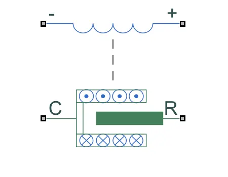
Figure 2 Solenoid block in Simscape
The block parameters such as rated voltage and current, pull-in force, air gap between R and C, spring constant, damping coefficient etc are user-defined. The motion under excitation can also be defined by the user – either the port R moves towards port C, or it moves away from port C. The block also contains an optional thermal port, which can be activated upon requirement, so that temperature dependence of the parameters can also be simulated.
The temperature control system consists of a thermistor to sense the temperature and based on the temperature the fan in the system is turned on and off. A thermistor is a type of resistance thermometer, or a resistor whose resistance varies with temperature. Thermistors are classified into two types: Negative Temperature Coefficient (NTC) and Positive Temperature Coefficient (PTC). When the temperature of an NTC thermistor rises, the resistance decreases. In contrast, as the temperature drops, resistance rises. This is the most common type of thermistor. A PTC thermistor operates in a slightly different manner. When the temperature rises, resistance rises, and when the temperature falls, resistance falls. This thermistor is commonly used as a fuse. Thermistors are simple to use, inexpensive, durable, and respond predictably to temperature changes. While they are not so suitable to be used in extremely hot or cold temperatures, they are the preferred sensor for applications that involves measuring temperature at a specific base point. They are well suited for applications that require extremely precise temperatures. Thermistors are used for a variety of applications such as in digital thermometers, in cars to measure oil and coolant temperatures, in ovens, refrigerators, etc. [2].
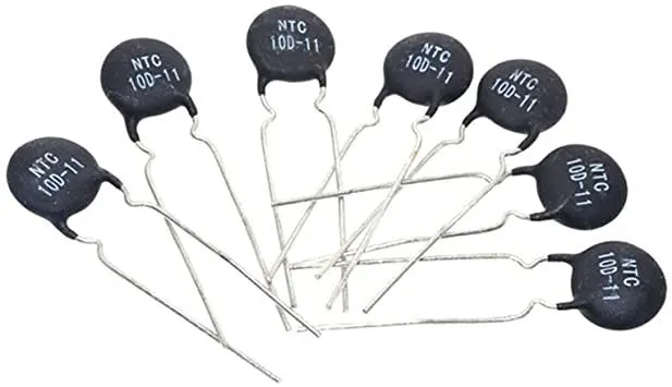
Figure 3 Thermistor
The thermistor block in Simscape represents a NTC thermistor. It consists of two types of ports: two electrical ports and a thermal port. The electrical ports comprise of the positive and negative terminals through which the electrical current flows. The thermal port represents the input temperature signal. The block parameters such as nominal resistance, reference temperature, characteristic temperature constant, thermal time constant, etc can be controlled by the user.
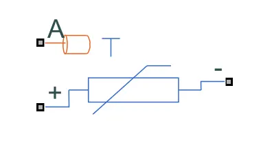
Figure 4 Thermistor block in Simscape
3. Key components and conditions
The doorbell model consists of a circuit with a solenoid, a battery to power the solenoid and a switch. When the switch is closed the solenoid receives electrical power from the battery and it pulls the metal arm to hit the bell, thereby producing sound (see the figure 5). In the simulation, the switch is closed for 2 seconds and then it is released. The focus of this simulation is to model the system and understand how the different components work. Therefore, for this simulation, the default block parameters of the blocks used, are only considered.
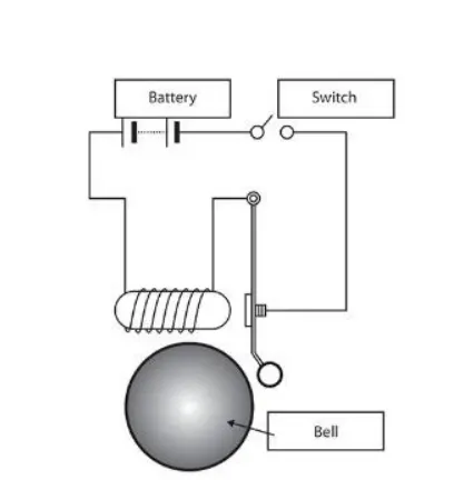
Figure 5 Doorbell model
The temperature control system uses a thermistor to detect the temperature of a heater and turns on or off a fan as per certain conditions. The conditions are – 20°C from 0 to 10 seconds, 27°C from 10 to 30 seconds and 23°C from 30 to 50 seconds, the fan turns ON for temperatures above 25°C and remains OFF in all other conditions. The model should show a circuit that turns on as per the above condition.
4. Modelling
- Doorbell model
In the doorbell model, a solenoid block is connected to a 12V battery block through a switch. The solenoid has a rated voltage of 50V and rated current of 0.5A (default parameters). It also contains a spring and a damper to control the movement of the plunger (port R). The default values of spring stiffness and damping coefficients are used here. The condition for the switch to be closed for 2 seconds and then be open, is achieved using a pulse generator. The pulse generator block produces square pulses at regular intervals. The parameter of the pulse generator is set such that it produces a pulse train of 4 seconds time period and 50% pulse width. A 2 second phase delay is also given to the pulse to observe the output better. This simulates the condition of the switch, where the switch remains on for 2 seconds (see Figure 6). This pulse is taken in as the input for the switch, whose threshold value is set as 0.5. So, whenever the value of the pulse is at 1, the switch is closed, thereby completing the circuit. The pulse from the pulse generator, which is a Simulink block, produces the signals as Simulink signals. It is therefore converted into a physical signal using a Simulink-PS Converter. The circuit is connected to an electrical reference, which represents an electrical ground.
To observe the physical movement of the plunger an ideal translational motion sensor block is connected to the mechanical ports of the solenoid. The physical signal output from the block is converted into a Simulink signal using a PS-Simulink converter. It is then connected to a Scope, to observe the output. A mechanical translational reference block is connected to the mechanical side of the solenoid. It acts as a reference point or a frame, for all the mechanical translational ports present.
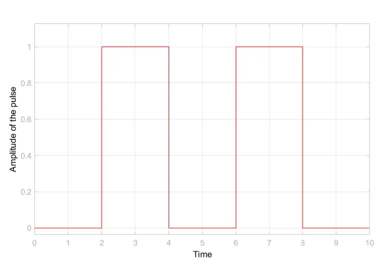
Figure 6 Pulse generated using the Pulse generator
Every physical network in a Simscape block diagram requires a solver for performing the simulation. It is used to specify the solver parameters that are necessary for the model before performing the simulation. A solver configuration block is therefore connected to the model. It can either be connected to the electrical side or the mechanical side. The default parameters of the solver block are used for this simulation. The total time simulation time is set as 10 seconds.
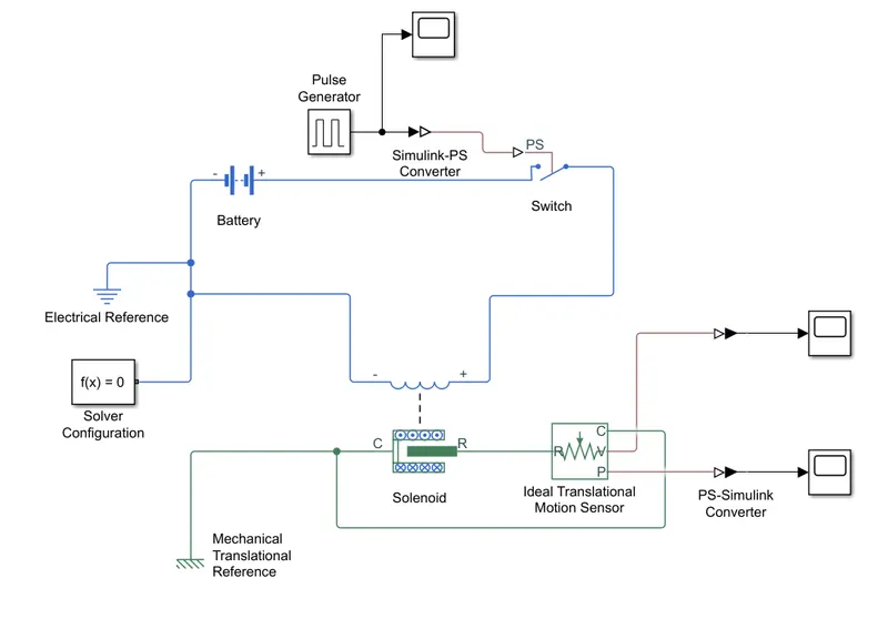
Figure 7 Block diagram of the Doorbell model
- Temperature control system
The electrical circuit of the temperature control system consists of a thermistor – to sense the temperature change, a 12V battery, a switch, a voltage sensor, and a current sensor. The thermistor block always requires a thermal input, which is provided here using a controlled temperature source block, which acts as an ideal energy source in a thermal network. This block is connected to a signal builder, which helps to create a signal as per the given conditions as explained in chapter 3. By providing the values specified in the given conditions, a signal can be created in the signal builder.
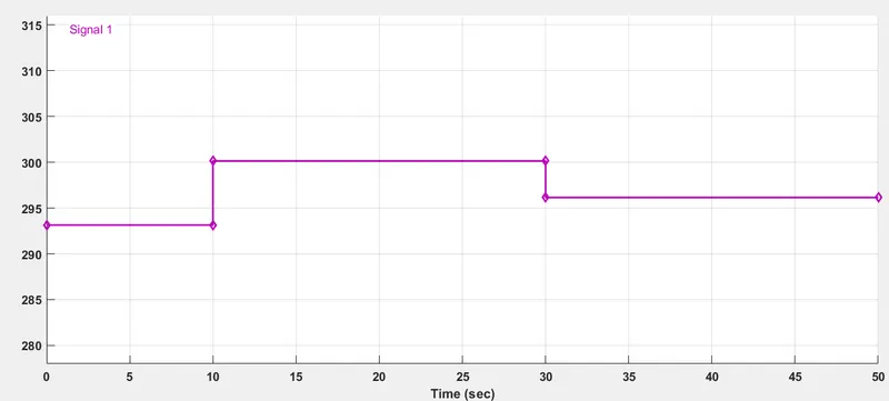
Figure 8 Signal created using Signal builder
This signal is then used as the input for the controlled temperature source block, which acts as a thermal energy source for the thermistor by keeping a controlled temperature difference irrespective of the heat flow rate. A thermal reference is also connected to the controlled temperature source block which acts as a reference point in a thermal network where the temperature is equal to absolute zero. The output from the signal builder is converted into a physical signal using a Simulink-PS Converter and a scope is also attached, to observe the signals. The input signal is also connected to the physical signal input port of the switch, in which the threshold is set as 298.15K (25°C). So, whenever the temperature in the input signal goes above the threshold, the electrical circuit is closed and current flows through it.
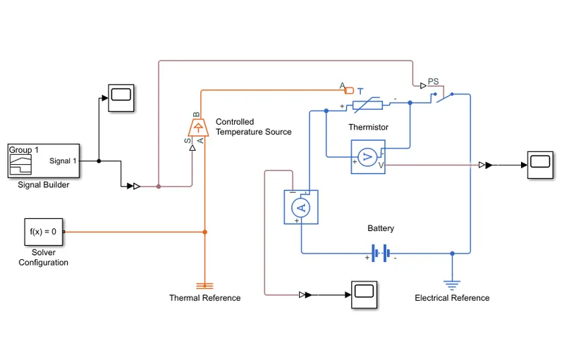
Figure 9 Block diagram of the Temperature control system
To understand the current flow through the circuit a current sensor is connected in series to the thermistor. A voltage sensor is also connected across the thermistor to observe the voltage drop across it. The outputs from both these sensors are converted to Simulink signals using a PS-Simulink Converter and are connected to respective scopes. An electrical reference is connected to the circuit to ground it. A solver configuration block is also attached to the model, to provide the necessary parameters for solving the model. The total simulation time is 50 seconds.
5. Results
The aim of the doorbell model was to observe the physical movement of the plunger. This was achieved by using the translational motion sensor block and connecting it to a scope.
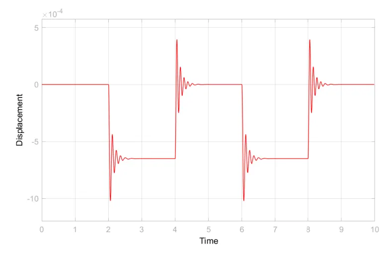
Figure 10 Displacement of the Plunger
It was clear from the output that the plunger undergoes oscillations every 2 seconds. This is because of the input signal. In the first 2 seconds, the plunger does not oscillate as there is a phase delay in the input signal. The plunger undergoes oscillations between 2 – 4 seconds, because during this period the input pulse turns the circuit ON, which activates the solenoid, attracting the plunger towards its C port. The plunger strikes the bell, undergoes small oscillations during process and eventually comes back to rest position due to the damper in the solenoid. Every time the circuit is completed, the plunger is attracted towards the bell and when the circuit is open, it returns to its initial position. During both this movements, the plunger undergoes oscillations (see Figure 10). By adjusting the damping coefficient, the time which the plunger oscillates can be varied.
The main condition for the temperature control system was that the circuit should turn ON when the temperature goes above 298.15K. As per the model created, the electrical circuit is completed or closed only when the temperature is above the threshold. This is achieved using the switch in the circuit. It was also clear from the current and voltage sensor that the circuit remains closed only during 10 – 30 seconds, the period in which the temperature is 300.15K (27°C). During all the other periods the circuit remains open (see Figure 10 and 11), that means no current flows through it.
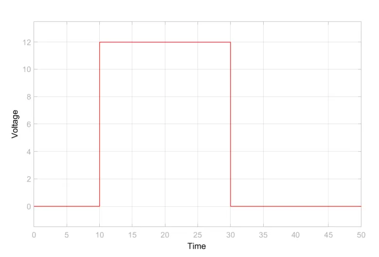
Figure 11 Voltage sensor output
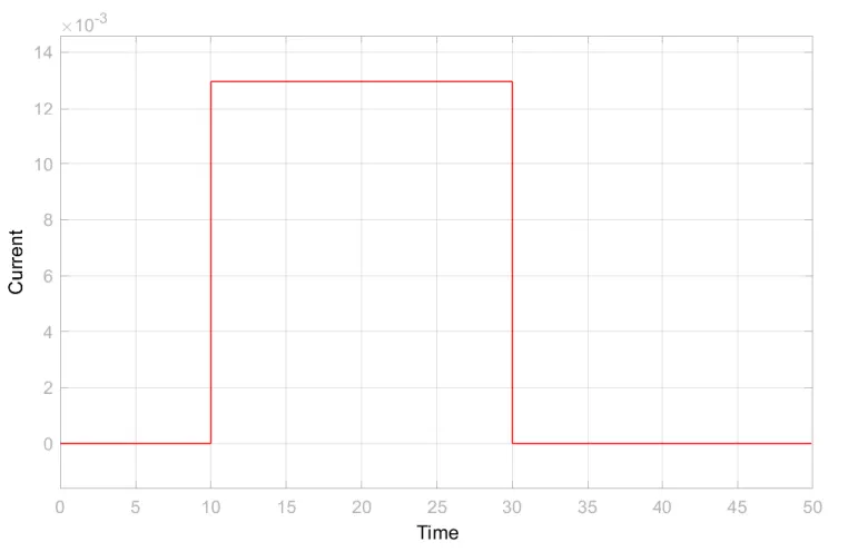
Figure 12 Current sensor output
By connecting a DC-Motor block to this circuit, the condition of the fan turning ON and OFF can be simulated. Since it is clear from the above figures that the temperature control system is functioning perfectly, the DC-Motor has not been included in this project.
6. Inference
The output of the doorbell model shows that the plunger undergoes oscillations every two seconds. From Figure 10, it is clear that all the oscillations are similar in nature. But this shouldn’t be true, because when the circuit is closed the plunger strikes the bell and when open it returns to its initial position. It maybe because the parameters used in this simulation are mostly the default values of all the blocks. The model is not based on any practical systems, rather it is just an example to understand the basics concepts of modelling in Simscape. This might be the reason why the results of the model may show some deviations from the actual physical concepts.
The temperature control system is also a very superficial model, as here too the simulation is done with default parameters of all the blocks. None of the data used are based on any practical experiments. Therefore, the results are only a representation of how the aim of the model can be achieved.
If experiments are performed and practical data are obtained, the accuracy of these models could be improved considerably. Since the onus was to understand the concepts of modelling, less importance was given to accuracy of the model.
The understanding of modelling in Simulink/Simscape was deepened through this project. The concepts like different elements needed in a model, connecting different blocks together, setting the parameters for the blocks, creating signals, and how to obtain the outputs from a model were all understood through this project.
7. Reference
[1] https://www.tlxtech.com/articles/solenoid-101-what-is-a-solenoid
[2] https://www.teamwavelength.com/thermistor-basics/
Original Report: https://drive.google.com/file/d/1USM-wfzkEGpo9Y1J7hSFXI5WId2dA0as/view?usp=sharing