Week -2
Aim of the projects is
Objective :- 1. To make a simulink mpodel of doorbell using a solenoid block in a situation where the switch is colsed for 2 seconds and then closed.
2.Use a thermistor to sense the temperature of a heater and turn ON if thwe temp is above 25C° and OFF otherwise.
DOOR BELL USING A SOLENOID BLOCK
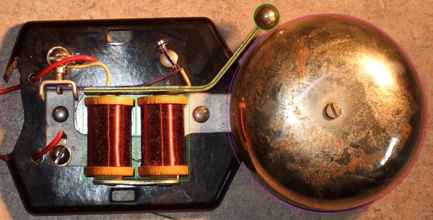
The above shown figure is the working of door bell using the solenoid.
This door bell is components of:
- thin clear green line: solenoids
- thin pink line: bell
- thick dark green line: clapper
- thin blue line: spring that holds the clapper and that gives electrical contact
- thick dark blue line: screw for adjusting the electrical contact
- oval thin red line: contact-area of opening contact
Function:
- Without current applied the bell is as shown in the photograph. The clapper is with some distance to the bell. The electrical contact is closed.
- When you apply current, the solenoids attract the clapper and the clapper strikes against the bell. The electrical contact opens. An electric arc starts between spring and contact-screw.
- The current decreases and the solenoids become too weak to keep the clapper in closed position. So the clapper swings back to initial position and closes the electrical contact again.
The solenoid is the simple electronic device that electric energy into mechanical work.
Simulink Model:-
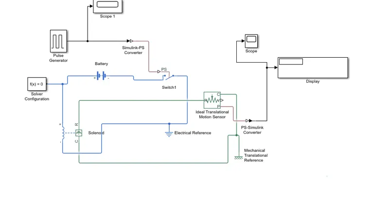
List of block is used in the block diagram:
Pluse generator,solver configuration, simulink ps conerter,
battery, scope,switch, solenoid ,electrical reference,ideal transmisson sensor, display
The input for the pluse genarator is give below
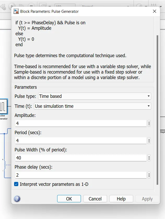
i have given the amplitude as 4 to achieve 2 seconds of phase delay and the time period as 4 seconds with a pluse width 40%.
The inputs signal which is fed into th electrical circuit . the output for the pluse generator and the physical signal is converted in to simulink signal the image has upload.
2.Thermistor theory:
Resistance thermometer is mainly depends on the temp.
simukink blocks ;
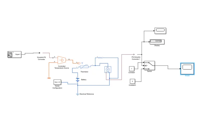
Lists of block were used in this block diagram:
1. signal bildier
2.simulink ps converter
3.controlled temp sensor
3.thermal reference
4.thermistor
5.battery
6.solver confriguation
7. electrical resistance
8. resistance
9.voltage sensor
10.ps simulink converter
11.switch
12.constant -2 nos
13. display
14. scope -2nos
here the inputs is fed through the block signal bulider . the input data is given based on the inital condition as give above in the challanges.
Temperature source: 20 °C from 0 to 10 seconds, 27 °C from 10 to 30 seconds, 23 °C from 30 to 50 seconds
Fan conditions: ON if the temperature above 25 °C, OFF otherwise
signal buliders:
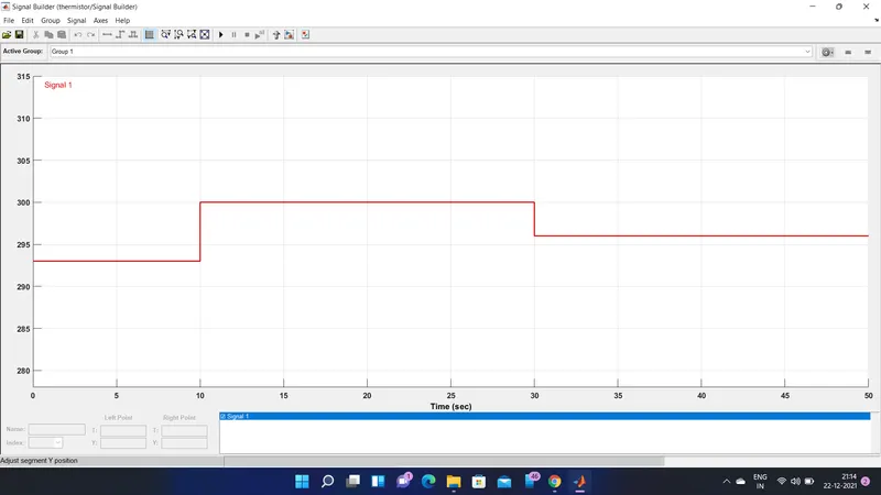
the signal is been fed into the controlled temp source. simulink physical signal convertor have to modified in the input handloing the filter input & derivatives has to be select instead of the signal has before.
then we have to the temparature range has 0-10 has 293.15k , for 10-30 has 300.15k and then for 30-50 has 296.15k. has show in the figure in the signal bulider.
Then the postive side of the thermistor is connected to the postive side of the battery and the negative side of the terminal is connected to the voltage sensor.
the value of the voltage sensor ios converted into the simulink signal using the convertor. The value is obtained in the display block. the final output is recorded in the scope.
The link for this challange is given below for both the objectives.
google drive link https://drive.google.com/drive/folders/1rHUbtl3yrqAZhFUxFDR_m9dco_ZsxE1g?usp=sharing