Week -2
Q.1) Make a Simulink model of Doorbell using solenoid block :
- Objectives:-
1.to understanding the door bell working
2.to simulate door model
3.to run the simulation of doorbell and obeserv plunger moment on scope block.
- Theory:
To run the simulation and make simulation blok we need to understand the proper working of door bell and also understand the equipment i.e. need to making the door bell therefore we can see the doorbell working as follows:
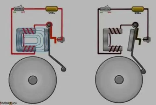
In above diagram see the two working conditions of door bell:
1.When switch in OFF Condition:
It consist of two wire wound on iron piece.spring loaded arm is kept closed to magnet the arm as hammer attage to it one end we called as clapper.the gang or bell also placed near the hammer their is one contact is placed near the clapper.(refer second fig.)
2.When switch in ON condition:
The clapper is can contact with scroove then circuit is complete and current goes through the coil due to current flow coil become an electromagnet.the electromagnet then pulls clapper towards to itself this hammer at the end clapper strikes the gang of the bell to produce sound.(refer fig first)
- For Simulating the model of door bell using Solenoid:
for simulate the diagram of door bell we need to open MATLAB then goes into Simulink button then window of simulink is open then click on create model firstly I was save my model as name doorbell_model.slx then I used the following block from library browers and connect this block and run the simulation :
- Block Used:
pulse generator, electric switch, battery, electrical refrence, solenoid, mechanical translational refrence, ideal translational motion sensor, solver configuration, PS simulink converter, simulink PS converter, scope block.
1.Pulse Genertaor:

The pulse generator blok generates square wave pulses at regular intervals. the block waveform parameter,Amplitude,Pulse width, period,phase delay determine the shape of output waveforms.the block output can be generated in timebased modes, determine by pulse type parameter.
2.Switch:

The block represents a switch controlled by an external physical signal. If the external physical signal PS is greater than the threshold, then the switch is closed, otherwise the switch is open.
3.Battery:
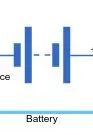
the battery is represent the simple battery model the block has four modeling varient.This block models a battery. If you select Infinite for the Battery charge capacity parameter, the block models the battery as a series internal resistance and a constant voltage source. If you select Finite for the Battery charge capacity parameter.
4.Electric refrences:
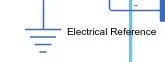
lectrical reference port. A model must contain at least one electrical reference port (electrical ground).
5.solenoid:
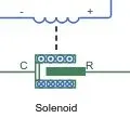
A solenoid is a device comprised of a coil of wire and movable plunger ,whenever electric current is introduced a magnetic field forms around the coil which draws the plunger in.a solenoid is a type of electromagnet that convert electrical energy to mechanical work.
6.mechanical translational refrence:
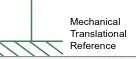
This block represents a mechanical translational reference point, that is, a frame or a ground. Use it to connect mechanical translational ports that are rigidly affixed to the frame (ground).
7.ideal translational motion sensor:
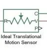
The ideal translation motion sensor block represent device that convert an across variable measured between two mechanical translational ports.all translational ports that are rigidly clamped to the frame (ground) must be connected to mechanical translational refrence clock.
8. solver configuration:

Each physical network represented bt connected simscape 'block diagram requires solver setting information for simulation the solver configuration block specifies the solver parameters that your model needs before you can begin simulation.
9.PS simulink converter:

The PS-simulink converter block converts aphysical signal into a simulink .output signal use this block to connnect outputs of asimscape physical network to simulink scopes or other blocks.
10.simulink PS converter:

the simulink to PS converter block convertes the input simulink signal to physical signal used this block icon changes dynamically based on whether it is connected to other blocks.
11.Scope:
scope block is used to display signals generated during simulation.its help to dispay the outputs inthe form of waves and also used to run the simulation.
- Simulation block diagram of door bell:
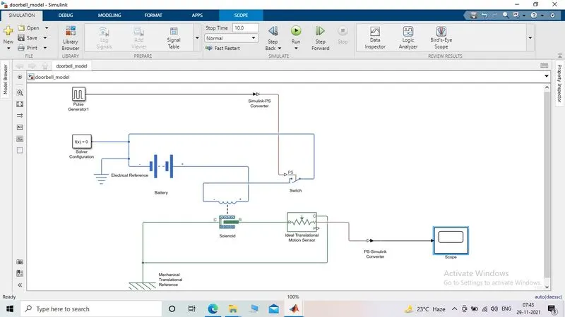
- Working:
- A battery is connected to switch and solenoid and electric refrence is needed to battery.
- mechanical refrence is also needed for the solenoid and pulse generator block is connect to switch.the pulse generator block is used to generate pulse for for when switch has to be pressed to close the circuit with time of 2 second.
- solver configuration is needed to specify the type.
- simulink PS converter is used to send physical system since pulse generator is simulink system therefore its connected to near the pulse generator,
- when circuit is closed the solenoid move from C to R and this moment is sensed by Ideal transitional motion sensor to provide the output to the scope block .
- output graph is plotted by scope block which is take from sensor with PS simulink convetor. in this way the door bell simulation can worked.
- Output from scope Block:
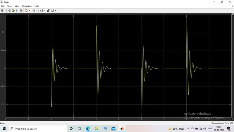
from above simulink model the scope is connected to ideal translation motion sensor block display the position of clapper at various time intervals,the bell start ringing at the interval of 2 second with given phase delay of 2 second.
- conclusion:
from this simulink model of door bell using ssolenoid. using this model physical phenomena is develop where switch is closed for 2 second and released also physical moment of clapper is observed by output block of scope.
Refrences:
for run this simulation I refer MATLAB library browers and MATLAB help (Mathworks and serch in it) also refer google and you tube for understanding the traditional door bell working and then simulate it in simulink.
Q.2) Use a thermistor to sense the temperature of a heater & turn on or turn off the fan as per the below conditions: Temperature source: 20 °C from 0 to 10 seconds, 27 °C from 10 to 30 seconds, 23 °C from 30 to 50 seconds
Fan conditions: ON if the temperature above 25 °C, OFF otherwise
ANS:
- Objectives:
1.to make simulink model for turn ON OFF the fan by using thermistor.and also run this simulation with following conditions:
- conditions:Temperature source:
20 °C from 0 to 10 seconds,
27 °C from 10 to 30 seconds,
23 °C from 30 to 50 seconds
Fan conditions: ON if the temperature above 25 °C, OFF otherwise
- Theory:
Thermistor:-
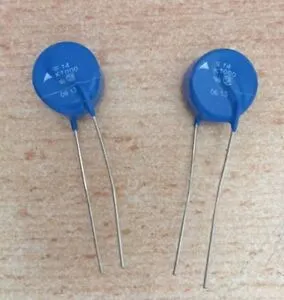
A thermistor is a type of resistor whose resistance is strongly dependent on temperature more so than in standard resistors. The word is a combination of thermal and resistor. Thermistors are widely used as inrush current limitors temperature sensor.
Types of thermitors:
Thermistor is mainly classify in two types:With NTC thermistors, resistance decreses as temperature rises, usually due to an increase in conduction electron bumped up by thermal agitation from the valence band. An NTC is commonly used as a temperature sensor or in series with a circuit as an inrush current limiter.
With PTC thermistors, resistance increases as temperature rises, usually due to increased thermal lattice agitations particularly those of impurities and imperfections. PTC thermistors are commonly installed in series with a circuit, and used to protect against overcurrent conditions, as resettable fuses.
- Simulink model:
- Output of Scope Block:
- Block used for simulation:
1.Signal builder block:

For build the signal I take signal builder block then double click on it the signal builer block is open then i set the timing of signal which is on xaxis in axes block n gives to commnd to it for 0-50 time then i goes to signal then in new and in new window i goes to custom block and set time and y axis limit (timr__[0 10 10 30 30 50],y-axis __[293 293 300 300 296 296] ) and apply then signal is build .The Signal Builder block allows you to create interchangeable groups of piecewise linear signal sources and use them in a model. You can quickly switch the signal groups into and out of a model to facilitate testing. In the Signal Builder window, create signals and define the output waveforms.
the signal builder giving input value as per the given conditions:
| At point 1 | time 0 sec | temprature-293k |
| At point 2 | time 10 sec | temprature-293k |
| At point 3 | time 30 sec | temprature-300k |
| At point 4 | time 30 sec | temprature-300k |
| At point 5 | time 30 sec | temprature-296k |
| At point 6 | time 50 sec | temprature-296k |
2.controlled temperature source:
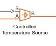
The Controlled Temperature Source block represents an ideal source of thermal energy that is powerful enough to maintain specified temperature difference across the source regardless of the heat flow consumed by the system.
Connections A and B are thermal conserving ports corresponding to the source inlet and outlet, respectively. Port S is a physical signal port, through which the control signal that drives the source is applied. You can use the entire variety of Simulink signal sources to generate the desired heat flow variation profile. The temperature differential across the source is directly proportional to the signal at the control port S. The block positive direction is from port A to port B. This means that the temperature differential is determined as TB – TA, where TB and TA are the temperatures at source ports.
s=temperature control signal
A= source inlet
B=source outlet
this block is represent ideal source of thermal energy that is power ful enough to maintain specified temperature diffrence across the source regardless of the heat flow consumed by the system.
3.Thermistor:

A thrmistor is type of resistor whose resistance is dependent on temperature more so than in standard resistor. the word is a combination of thermal and resistor.
4.Resistor:

The resistor block models a linear resistor described with following equation:
V=I.R
where V-voltage
I-current
R-resistor.
5.electric refrance:
electric refrance block represents an electric ground electrical conserving portes of all block that directly connected to this block.
6. dc voltage source:
The Voltage Source block implements a voltage source with DC, AC, and noise components.
7.Voltage sensor:
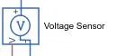
The block represents an ideal voltage sensor, that is, a device that converts voltage measured between any electrical connections into a physical signal proportional to the voltage. Connections + and - are conserving electrical ports through which the sensor is connected to the circuit. Connection V is a physical signal port that outputs voltage value.
8.thermal refrennce:
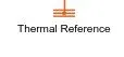
This block represents a reference point in a thermal network where the temperature is equal to absolute zero.
9.Simulink to PS coveter:

Converts the Simulink input signal to a Physical Signal. The unit expression in 'Input signal unit' parameter is associated with the Simulink input signal and determines the unit assigned to the Physical Signal.
10.PS to simulink converter:

Converts the input Physical Signal to a Simulink output signal. The unit expression in 'Output signal unit' parameter must match or be commensurate with the unit of the Physical Signal and determines the conversion from the Physical Signal to the Simulink output signal.
11.Solver configuration:

Each physical network represented by a connected Simscape™ block diagram requires solver settings information for simulation. The Solver Configuration block specifies the solver parameters that your model needs before you can begin simulation. Each topologically distinct Simscape block diagram requires exactly one Solver Configuration block to be connected to it.
12.Constant block:
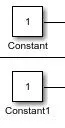
The Constant block generates a real or complex constant value signal. Use this block to provide a constant signal input. The block generates scalar, vector, or matrix output, depending The dimensionality of the Constant value parameter The setting of the Interpret vector parameters as 1-D parameter.
13.scope:
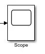
scope block is used to display signals generated during simulation.its help to dispay the outputs inthe form of waves and also used to run the simulation.
14.DC motor:
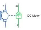
This block represents the electrical and torque characteristics of a DC motor. The block assumes that no electromagnetic energy is lost, and hence the back-emf and torque constants have the same numerical value when in SI units. Motor parameters can either be specified directly, or derived from no-load speed and stall torque. If no information is available on armature inductance, this parameter can be set to some small non-zero value. When a positive current flows from the electrical + to - ports, a positive torque acts from the mechanical C to R ports. Motor torque direction can be changed by altering the sign of the back-emf or torque constants.
15.Ideal rotational motion sensor:
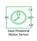
This block measures angular velocity or angle in a mechanical rotational network. The sensor is ideal since it does not account for inertia, friction, delays, energy consumption, and so on. The physical signal ports W and A report the angular velocity and angle, respectively, of port R relative to port C. The measured angular velocity is positive when the angular velocity at port R is greater than the angular velocity at port C.
16. Temperature sensor:
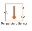
This block measures temperature in a thermal network. There is no heat flow through the sensor. The physical signal port T reports the temperature difference across the sensor. The measurement is positive when the temperature at port A is greater than the temperature at port B.
17.Mechanical refrence:
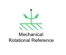
This block represents a mechanical rotational reference point, that is, a frame or a ground. Use it to connect mechanical rotational ports that are rigidly affixed to the frame (ground).
- Working of Model:
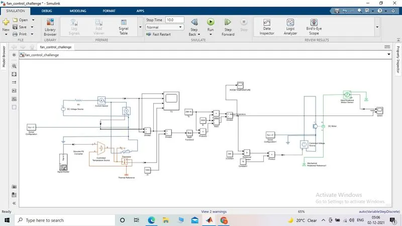
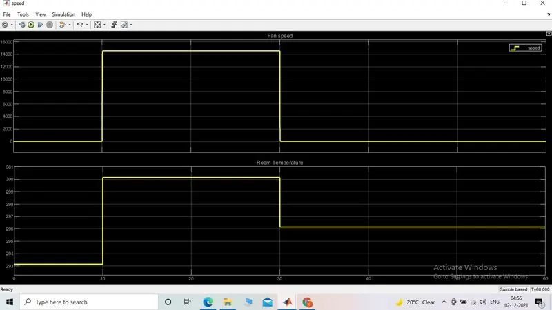
As per conddition of temperature 20 °C from 0 to 10 seconds, 27 °C from 10 to 30 seconds, 23 °C from 30 to 50 seconds these value are provided as input to signal builder block then output from this block is convert to physical to simulink converter then it gives to controlled temperature source it can control and mentain the specified temperature difference across the source.then input temperature flow through thermistor.thermistor is connect with resistor and voltage across resistor by +V -V. connect positive terminal of voltage source to positive terminal of thermistor and connect negative terminal of voltage sensor and restistor to get value from voltage sensor.output terminal of voltage sensor is connected with switch parameter for giving conditions as fan must ON if temperature above 25°C OFF otherwise output is sucessfully execute by scope block.In next ckt the voltage controlled source gives to the dc motor only if the switch return 1 as value and our motor connected to fan to turn on.now to detect the motion of motion an ideal rotational motion sensor is attached to R and C port of the rotor and casing and it return the angular velocity and displacement of the motor for the time period.
- Conclusions:
We used thermistor to sence the temperature and according to our conditions we put the threshould value to the switch block to turn ON and OFF the fan at a pirticular temperature.
Refrences:
for run this simulation I refer MATLAB library browers and MATLAB help (Mathworks and serch in it) also refer google and you tube for understanding the working of thermistor and temperature sensor and then simulate it in simulink and also my suport engineer Mr. Shrinivas sir guide me for run this simultion.