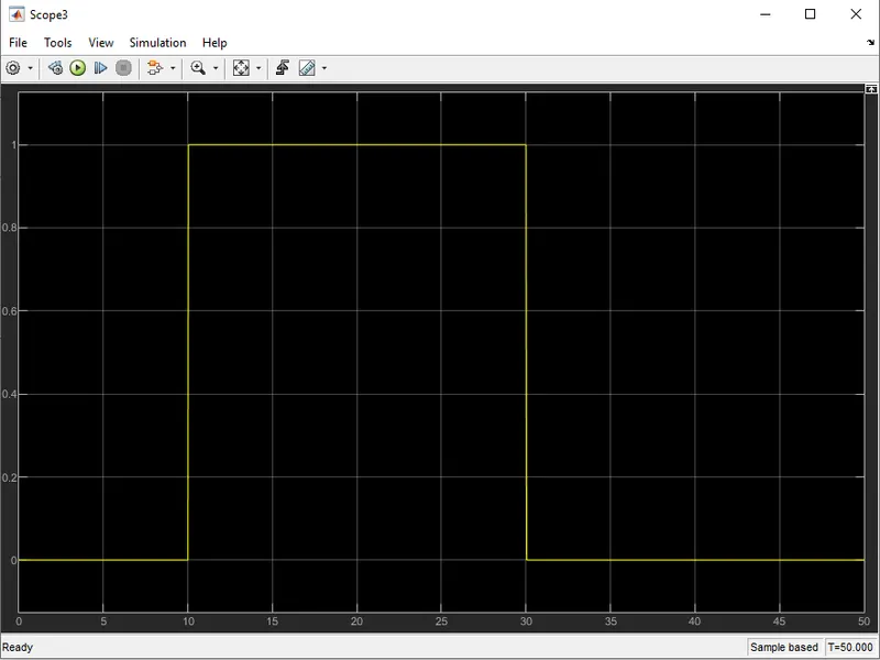
Week -2
OBJECTIVE :
- Make a Simulink model of Doorbell using solenoid block with the following details:
In the above arrangement, when the switch is closed the electromagnet receives electrical power from the battery and pulls the metal arm to hit the bell producing sound.
Create a situation where the switch is closed for 2 seconds and then released. Observe the physical movement of the plunger. Assume remaining parameters.
2. Use a thermistor to sense the temperature of a heater & turn on or turn off the fan as per the below conditions:
Temperature source: 20 °C from 0 to 10 seconds, 27 °C from 10 to 30 seconds, 23 °C from 30 to 50 seconds
Fan conditions: ON if the temperature above 25 °C, OFF otherwise
| MODEL 1 : Simulink model of Doorbell using solenoid block |
WORKING PRINCIPLE :
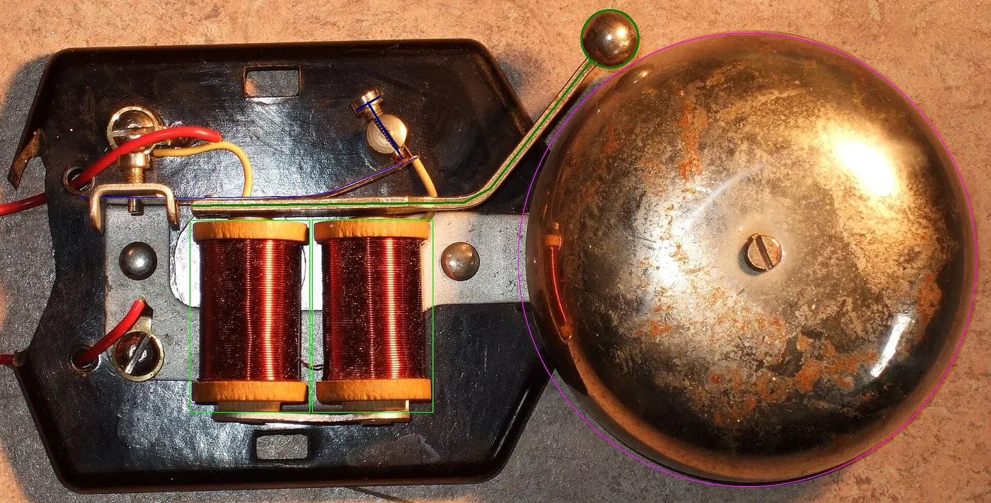
The doorbell uses a electromagnet called a solenoid. A solenoid is an electomagnet where the coiled wire surrounds a metal piston. The piston contains magnetically conductive metal, so it can be moved backward or forward by the electromagnetic field.
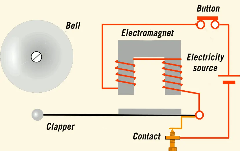 |
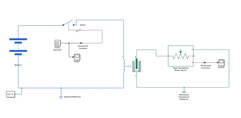
In our model , a square pulse is generated with a time delay of 2 seconds and is passed to the switch control. Now the switch block is controlled by the pulse generator. When the threshold value is less than the Physical signal value the switch closes and forms a closed circuit. The electric current is passed from the battery to the solenoid as soon as the circuit is closed . The solenoid contains a piston consists of iron core mounted on nonmetallic metal bar. When there is no power to the electromagnet, a spring pushes back the piston , and the iron core remains outside of the wire coil. When we turn ON the electromagnet by passing current, the iron core is drawn into the magnetic field. The iron core slides into the coil and strikes the end of the piston to the one hand tone bar which vibrates and produces the “ding” sound. As long we hold the doorbell button, the current will flow through the electro magnet and the piston remains in this position. Here the generated pulse is supplied to switch for a period of 2 seconds. So after two seconds get over the connection breaks and circuit becomes open. That means current will stop flowing through the electro magnet and the magnetic field collapse. The spring snaps the piston back to the initial position, where it hits the other tone bar on the other side. The second tone bar produces the “dong” sound. The process repeats until the last pulse of signal is generated.
The total time for signal is set for 10 seconds and pulse generated for every 2 seconds. During this period how the bell rings on and off is shown in the graph scope 1 and 2.
The ideal transformer motion sensor is used to monitor the position and velocity of plunger which is nothing but the piston for each pulse. The displacement and velocity values are shown in the display block.
Electrical and mechanical reference were given to each mechanical and electrical systems . A solver is provided to compute the states of the model during simulation or code generation.
|
|
 \
\PRE-REQUISTES :
|
1. Pulse Generator: |
 |
The Pulse Generator block generates square wave pulses at regular intervals. The block waveform parameters, Amplitude, Pulse Width, Period, and Phase delay, determine the shape of the output waveform. |
| 2. Simulink-PS Converter: |  |
Converts the unitless Simulink input signal to a Physical Signal. |
| 3. Scope: |  |
Display signals generated during simulation. |
|
4. Switch: |
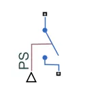 |
Switch controlled by an external physical signal. |
|
5. Battery: |
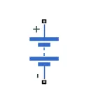 |
The Battery block represents a simple battery model. |
|
6. Solenoid: |
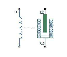 |
Model electrical characteristics and generated force of solenoid. |
|
7. Ideal Translational Motion Sensor: |
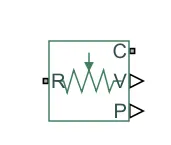 |
The Ideal Translational Motion Sensor block represents a device that converts an across variable measured between two mechanical translational nodes into a control signal proportional to velocity or position. You can specify the initial position (offset) as a block parameter. The sensor is ideal since it does not account for inertia, friction, delays, energy consumption, and so on. |
|
8. Mechanical Translational Reference: |
 |
The Mechanical Translational Reference block represents a reference point, or frame, for all mechanical translational ports. All translational ports that are rigidly clamped to the frame (ground) must be connected to a Mechanical Translational Reference block. |
|
9. Electrical Reference: |
 |
The Electrical Reference block represents an electrical ground. Electrical conserving ports of all the blocks that are directly connected to the ground must be connected to an Electrical Reference block. A model with electrical elements must contain at least one Electrical Reference block. |
|
10. Solver Configuration: |
 |
The Solver Configuration block specifies the solver parameters that your model needs before you can begin the simulation. |
| 11. PS-Simulink Converter: |  |
Convert physical signal into Simulink output signal |
PROCEDURE :
Step 1 :
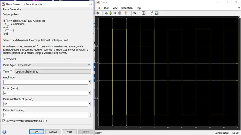
first we have to give an input signal so we will be using Pulse Generator block to provide input square shaped waveform at regular intervals. Then, we have altered the parameters by keeping amplitude as 1, period of signal as 4 sec, Pulse width of 50% and phase delay of 2 sec.This means that initially the pulse will be zero and at 2 secs, the pulse width will be half of period(50%), so for the next two seconds the pulse will be at amplitude ’1’ only, then it will again come down to zero at 4th second and then it will at zero for next 2 secs thus completing the periods of 4 seconds.
From starting to ending of the pulse will take 4 secs of time periods in which only for 2 secs the amplitude will be one and for rest of time it will be zero. So, after these 4 secs period again the pulse will be generated and thus cycle continues.To this ‘Pulse Generator block’ a ‘Scope block’ is connected to see how the pulse is generated.
As mentioned before, the pulse has started after 2 seconds, then for next two seconds it has amplitude of ‘1’ and then next 2 seconds the pulse is again zero. The pulse is starting from 2 seconds and ending at 6 seconds which nothing but a time period of 2 seconds.Thus, this represents that when amplitude is one, the switch will be closed and when it is zero the switch will open. Since our objective is only to see the change in position of plunger when switch is closed for 2 seconds so that we have the amplitude as 1 for 2 seconds in the pulse generator by making the pulse width half of the period in the inputs for ‘Pulse Generation block’.
after that we have used Simulink-PS converter block because switch block requires an external physical signal to operate. If external physical signal applied is greater than threshold value, then switch is closed otherwise it is open.Further, we have taken Solenoid block and connected positive terminal of Solenoid block with positive terminal of Battery. Also, we have connected negative terminal of solenoid block to negative terminal of battery block.
Now, the battery, switch and solenoid block is connected to ‘Electrical Reference block’ which represents the earthing of the circuit. The ‘Electrical Reference block’ should be connected with the negative terminal of the ‘Battery block’. in the ‘Solenoid block’, ‘R’ and ‘C’ are two variables which represent the Plunger and fixed point respectively.Now this ‘R’ is connected to an ‘R of the ‘Ideal Translational Motion Sensor block’, which senses the position of the plunger in the ‘Solenoid block’ and gives the output.in the ‘Ideal Translational Motion Sensor block’, the outputs are given as V and P which represent the velocity and the position of the plunger. Since, we need to observe only the position of the plunger, we need the results from ‘P’ output.
the ‘C’ in the ‘Ideal Translational Motion Sensor block’ represents the mechanical translational conversion port which means that the mechanical process starts from ‘R’ and ends at ‘C’ and it again starts from ‘R’ and the cycle goes on.So ‘C’ in the ‘Ideal Translational Motion Sensor block’ is connected to a ‘Mechanical Translational Reference block’ which represents a fixed point where it is rigidly clamped in real time.Similarly, ‘C’ of the solenoid block is also connected to the same ‘Mechanical Translational Reference block’ as fixed point for the solenoid.
Since, we need the position of the plunger as output from ‘Ideal Translational Motion Sensor block’, so we have connected the port ‘P’ to a ‘PS-Simulink Converter block’ where the physical values of the port ‘P’ are converted to Simulink value which is connected to the ‘Scope block’ for generating the graph of the change in the position of the plunger from port ‘P’ of ‘Ideal Translational Motion Sensor block’.As mentioned above the port ‘P’ of ‘Ideal Translational Motion Sensor block’ is connected to another ‘Scope block’, and a ‘Solver Configuration block’ is also connected to this path which generates equations and solves the whole model internally to give the results of the whole Simulink model as output.
Here we can see that the switch is closed for 2 seconds and after that switch is open. Amplitude= 0 means the switch is closed. It can also be seen that the plunger strikes after every 2 seconds. The motion of the plunger was simulated and recorded and plotted in scope.
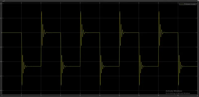
The above graph determines the position of plunger at the start of 2 seconds and end by 4th second. When the piston moves back it again hits the other end, vibrates and produces another bell sound and remains in its position until the next pulse passed. This repeats till the 10 seconds. At the start of 2 seconds the piston moved from initial position where initial position is set as zero to -234.672micro meters. At the end of 4 seconds the circuit breaks the piston moves back to initial position i.e.,zero position where it again hits the other end metal bar with force and produces another vibration wave.
MODEL 2 : THERMISTOR MODEL
Use a thermistor to sense the temperature of a heater & turn on or turn off the fan as per the below conditions:
Temperature source: 20 °C from 0 to 10 seconds, 27 °C from 10 to 30 seconds, 23 °C from 30 to 50 seconds
Fan conditions: ON if the temperature above 25 °C, OFF otherwise
PREREQUISITES :
|
Thermistor |
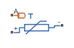 |
R=R0exp(B(1/T−1/T0)) where:
The following equation describes the thermal behavior of the block: Q=Kd*tc*dT/dt where:
|
| Signal builder | 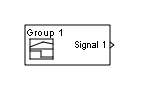 |
The Signal Builder block allows you to create interchangeable groups of piecewise linear signal sources and use them in a model. You can quickly switch the signal groups into and out of a model to facilitate testing. In the Signal Builder window, create signals and define the output waveforms. |
| Scope: | |
Display signals generated during simulation. |
|
4. Switch: |
 |
The Switch block passes through the first input or the third input signal based on the value of the second input. The first and third inputs are data input. The second input is a control input. Specify the condition under which the block passes the first input by using the Criteria for passing first input and Threshold parameters. Pass through input 1 when input 2 satisfies the selected criterion; otherwise, pass through input 3. The inputs are numbered top to bottom (or left to right). The first and third input ports are data ports, and the second input port is the control port. The criteria for control port 2 are u2 >= Threshold, u2 > Threshold or u2 ~= 0. |
|
5. Battery: |
|
The Battery block represents a simple battery model. |
|
6. Solenoid: |
|
Model electrical characteristics and generated force of solenoid. |
| Resistor | 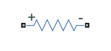 |
The voltage-current (V-I) relationship for a linear resistor is V=I*R, where R is the constant resistance in ohms. The positive and negative terminals of the resistor are denoted by the + and - signs respectively. By convention, the voltage across the resistor is given by V(+)-V(-), and the sign of the current is positive when flowing through the device from the positive to the negative terminal. This convention ensures that the power absorbed by a resistor is always positive. |
| Voltage Sensor |  |
The block represents an ideal voltage sensor, that is, a device that converts voltage measured between any electrical connections into a physical signal proportional to the voltage. Connections + and - are conserving electrical ports through which the sensor is connected to the circuit. Connection V is a physical signal port that outputs voltage value. |
|
Controlled temperature source |
 |
The Controlled Temperature Source block represents an ideal source of thermal energy that is powerful enough to maintain specified temperature difference across the source regardless of the heat flow consumed by the system. |
| Constant Block | 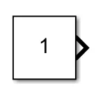 |
Output the constant specified by the 'Constant value' parameter. If 'Constant value' is a vector and 'Interpret vector parameters as 1-D' is on, treat the constant value as a 1-D array. Otherwise, output a matrix with the same dimensions as the constant value. |
|
8. Mechanical Translational Reference: |
|
The Mechanical Translational Reference block represents a reference point, or frame, for all mechanical translational ports. All translational ports that are rigidly clamped to the frame (ground) must be connected to a Mechanical Translational Reference block. |
|
9. Electrical Reference: |
|
The Electrical Reference block represents an electrical ground. Electrical conserving ports of all the blocks that are directly connected to the ground must be connected to an Electrical Reference block. A model with electrical elements must contain at least one Electrical Reference block. |
|
10. Solver Configuration: |
|
The Solver Configuration block specifies the solver parameters that your model needs before you can begin the simulation. |
| 11. PS-Simulink Converter: | |
Convert physical signal into Simulink output signal |
PROCEDURE :
first we have to make a signal by dragging signal builder block to the workspace so that we can give input that dependent to time i.e.,
- For 0-10 sec, temperature = 20 degree celcius
- For 10-30 sec, temperature = 27 degree celcius
- For 30-50 sec, temperature = 23 degree celcius
from the help menu we have known that the controlled temperature source and thermistor block only takes values in Kelvin, hence we have converted those temperature values into kelvin and made the Signal builder block as shown below.
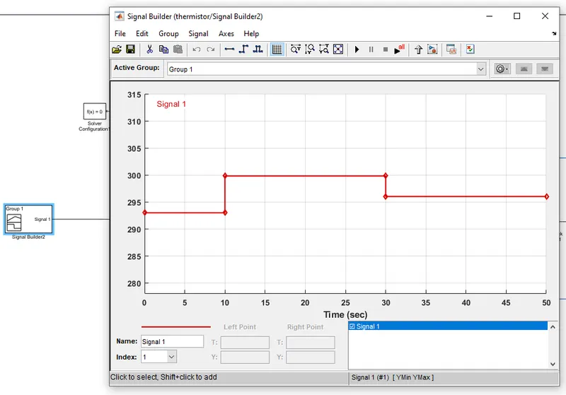
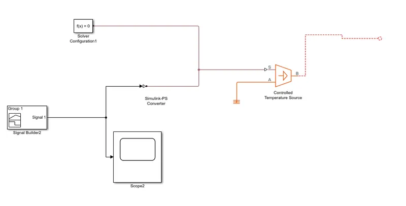
after then we will connect Signal builder block to Simulink-PS converter block since controlled temperature source takes only physical control signal as input.then we will connect output terminal B of controlled temperature source to thermal port A of Thermistor block.
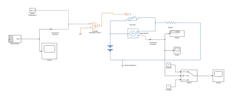
We have taken the Thermistor block to sense the temperature of circuit. Further, we have connected positive terminal of thermistor to positive terminal of battery. Here, we have used battery block as a DC voltage source. Thereafter, we have connected voltage sensor parallel to thermistor block to measure the voltage across the circuit and converts those measured voltage value into a physical signal proportional to the voltage. We have also used resistor block to provide resistance to electric flow of current.
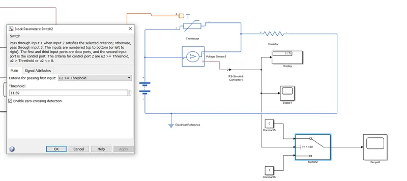
Due to this, Physical signal port V of voltage sensor generated threshold voltage for given temperature conditions. However, it is physical signal. Hence, we have used PS-simulink converter to convert those physical signal into Simulink signal.
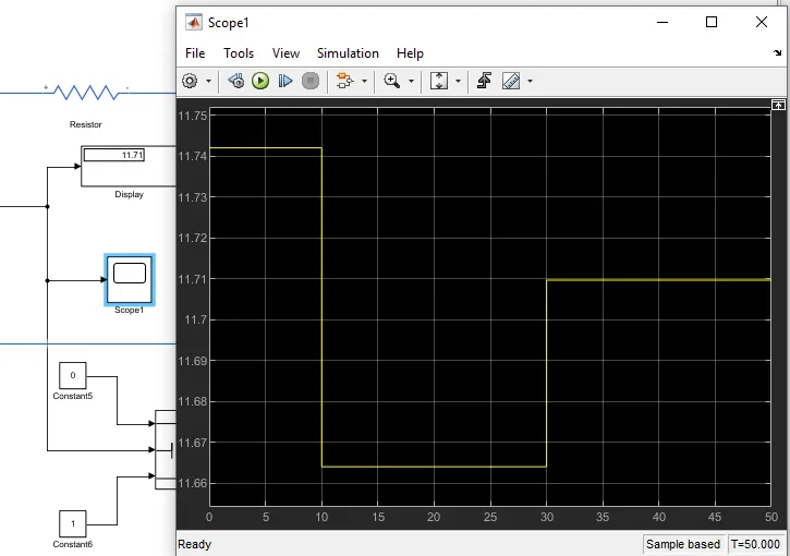
As per the fan conditions given in question states that fan should be on if temperature goes above 25 deg. celicus i.e. 298.13 K. Hence, we have introduced one constant block resembling temperature of 25 deg. celcuis and then calculated the threshold voltage as 11.92 required to trigger the switch so that mentioned fan condition can be satisfied. We have used scope block and connected to the output port V of voltage sensor & PS-simulink converter to see the voltage graph of given temperature conditions and is as under;
8. From the above graph, it was very evident that for time (0-10 sec), voltage is around 11.935 V at temperature 293.13 K. Further, it was observed that for time(10-30 sec), voltage is around 11.91 V at temperature 300.13 K and for time(30-50 sec), voltage is around 11.9225 v at temperature 296.13 K. Hence, we can say that as soon as temperature increases in the circuit, voltage values decreases.
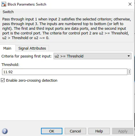
10. Further, we have connected voltage signal to port 2 of switch block. Here, we have have given threshold voltage value as 11.92 because as per fan condition, fan should be on when temperature goes above 25 deg. celcius.
11. Switch block has a condition such that when control signal port U2 is greater than or equal to threshold value, it passess through port 1 otherwise it passes through port 3.
Hence, we can say that when temperature value is greater than 25 deg. celcius, voltage value will be less than threshold voltage value hence for that particular instance of the signal, the signal passess through port 3. Hence, for port 3, we have connected constant block of value as '1' as true condition and fan will switch on. Further, when temperature value is less than 25 deg. celcius, voltage value will be more that threshold voltage value, hence for that particular instance of signal, the signal passess trough port 1. Hence, for port 1, we have connected constant block of value as '0' as false condition and fan will be switched off.Scope block has been connected to output port of switch so that output graph can be observed.
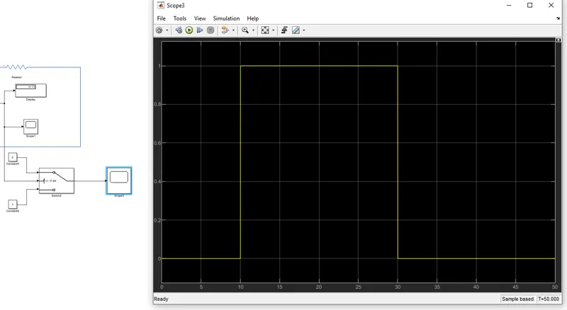
Outputplot :