Week -2
- Doorbell using solenoid block
Aim: To make doorbell Simulink model using solenoid block
Solenoid: It is an arrangement of coil and material. Bypassing a current through the coil magnetic field is generated which attracts or pulls the material like a permanent magnet. When current not passed spring is utilized to return the material to its previous position. This phenomenon is used in the doorbell to pull the mechanical arm which hits the ball to produce sound.
Simulink model
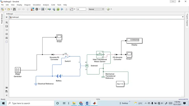
Fig 1: Simulink model representation of doorbell
A pulse generator is used to turn on and turn off switch 1 as shown in above Fig 1. It was set as an input signal for the first 2 seconds pulse is high and the next two seconds pulse is low to satisfy the given condition as shown in Fig 2. A Simulink-PS convertor was used to convert the Simulink signal to a physical system signal. A Battery was connected to excite the solenoid. Electric reference was given to initialize the condition for electrical physical systems. When the pulse is high above the threshold value of 0.5 the switch got itself closed. The plunger in solenoid moves which is observed using an ideal translational motion sensor that is connected to the scope and display block to generate the results. Solver configuration is used to solve the equations of each physical system. The simulation was carried out for 10 seconds.
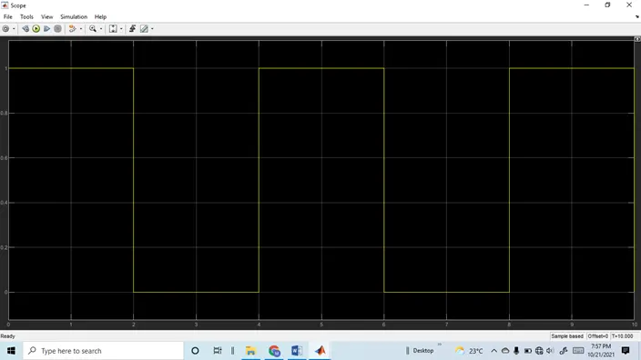
Fig 2.Input pulse signal
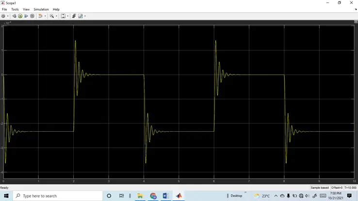
Fig 3. Output signal
When the pulse signal is high the plunger moved downward and it’s retained its original position when the pulse is low. Spikes can be seen due to the initial current flow and spring, plunger slightly oscillates.
2. Fan controlled by a thermistor
Aim: To make the Simulink model turn off and on the fan based on given temperature conditions
Simulink model
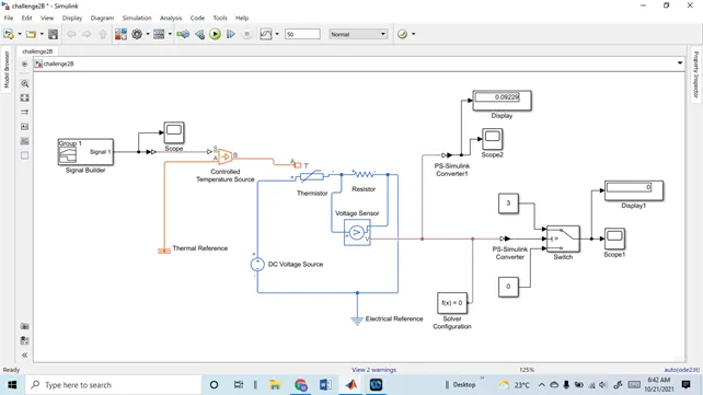
Fig 1 Fan switch on and off based on the temperature of the heater
The given temperature was given in oC that was converted into kelvin. The three temperature given as inputs are 20 oC,27 oC, 23 oC converted into 293 K,300 K,296 K for 0-10 sec,10-30 sec, 30-50 sec respectively as shown in Fig 2. A signal builder is used for temperature signals along with a controlled temperature source. This temperature is assumed as heaters temperature and the thermistor senses these temperatures. A voltage sensor is a connected parallel to the resistor to measure the voltage during simulation. To find out the voltage for temp 25 oC (298K) separately constant temperature source was utilized and found the voltage was 0.0999 v this was set as a threshold voltage for the switch to on and off respectively. The simulation was carried out for 50 sec.
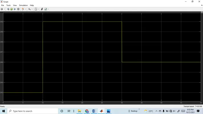
Fig 2 Input temperature signal
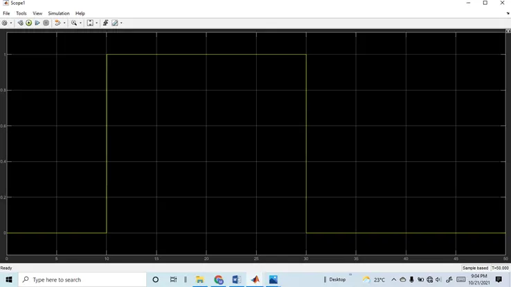
Fig 3 Output of switch (On/Off) with respect to input temperature
From Fig 3 the switch is turned on only from 10-30 sec period of simulation, during that period the temp was 300 K which satisfied the threshold temp of more than 298 k.