Make a Simulink Model of Door-bell and Fan.
Make a Simulink Model of Door-bell and Fan.
Que1:- Make a simulink model of door bell using solenoid block with the following scenario.
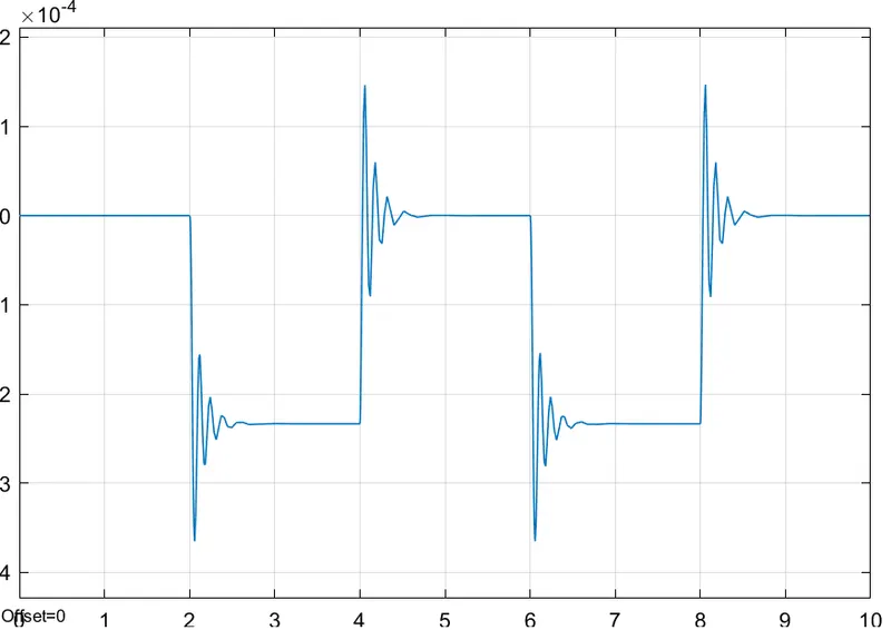
Scenario:- In the Doorbell arrangement when the switch is closed the electromagnet receives electrical power from the battery and pulls the metal arm to hit the bell producing sound. Create situation where the switch is closed for 2 seconds and then realeased. Observe the physical movement of th plunger.
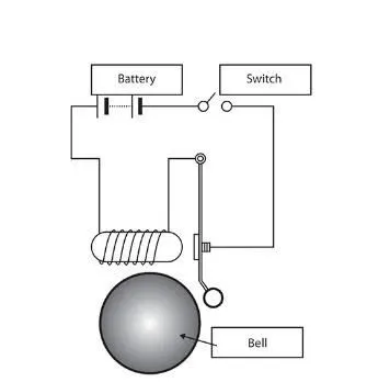
Solenoid Block:- This block implements the electrical and mechanical characteristics of a solenoid. In this th plunger maximum stroke is implemented as a hard stop th edynamics of which are set by the contact stiffness and contact damping parameters. The sam parameters are used to model the contact dynamics when th plunger pulls fully in. The spring constant parameter is used to implement a spring force the tpulls the plunger out and can be set zero.
This Blocks Are used in this model:-
1] Pulse generator
2] Simulink to PS converter
3] PS to Simulink converter
4] Solenoid
5] Ideal Translational Motion Sensor
6] Mechanical Translational Reference
7] Solver Configuration
8] Basic Blocks
Model:-
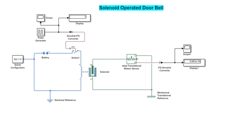
Explanation:-
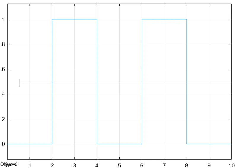
In this we used pulse generator block for generate a square pulse. so we give period value as 4 seconds, pulse width is 50 % of period,phase delay as 2 seconds and amplitude by default of is 1 we have not change it. This means that initially the pulse will be zero since we have given phase delay as 2 sec so till 2 sec the pulse will be zero then the pulse will start from 0 to 1. Then we given amplitude as 1 and then now the pulse width will half of period so for the next two seconds the pulse will be at amplitude 1 then it will again come down to zero at 4th seconds then it will be at zero for next 2 seconds thus completing the period of 4 sec. From starting to end of the pulse will take 4 seconds of time period in which only for 2 seconds the amplitude will be one and for rest of time will be zero so after this 4 sec period again the pulse generated.
Result:-
1] this figure shhows the how the pulse generated.
Obesrvation:-
In this the change in position of the plunger there are some waves forms at the start of the changes in position so its reduce using solenoid block for spring constant value and increase the damping coefficient.
2] Use a thermistor to sense the temperature of a heater & turn on or turn off the fan as per below conditions:
Scenario:- Temperature source- 1] 20 °C from 0 to 10 seconds
2] 27 °C from 10 to 30 seconds
3] 23 °C from 30 to 50 seconds
Fan conditions: ON if the temperature above 25 °C, OFF otherwise.
Thermistor:- A thermistor is a resistance thermometer or a resistor whose resistance is dependent on temperture. The term is combination of thermal and resistor. When temperature increases the resistance increases and when temperature decrease resistance decrease. this type of thermistor is generally used as a fused. The basic principle of thermistor is itys dependency on resistance values on the change in temperature. The value of resistance can be measured by using an ohm meter. this are connected in series with the battery and the meter. It is used for sensing and help to regulate cold and heat.
This Blocks Are used in this model:-
1] Thermistor
2] Resister
3] Signal Builder
4] Voltage sensor
5] controlled temperature source
6] Thermal referance and electrical referance
7] Simulink to PS converter and PS to simulink coverter
8] Switch and some basic blocks.
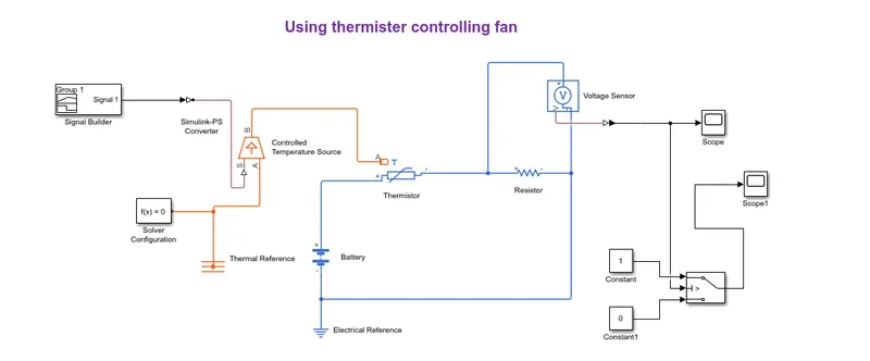
Model:-
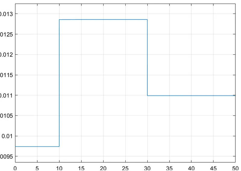
Graph 1:-
Explanation:-
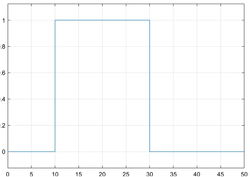
In thermistor variable change low to high. It connect negative port to positive port of resistor and positive port is connect to positive port of battery. then the battery negative port is connect to ele. referance (Earthing). The resistor negative port is connect to volatge sensor in way of parrallel. then the basic circuit is complete. so then we need to give inputs so calling signal builder and in this create a new signal as per scenario. then call simulink PS converter for converting signals into physical quantities . It connect to controlled temperature source at port of S and the bB port is connect to thermistor A port then give solver to circuit. then run the simulatin and we will meet one graph in this graph we can see how to voltage is changinhg with changing of temperature using this information we can set conditions for fan ON/OFF. In this we can observe the graph as time 0 to 10 sec when temp is 293k voltage is betn the 0.0095 and 0.01, time 10 to 30 when temp is 300k the voltage is betn 0.0125 and 0.013 and from time 30 to 50 at temp 296 the voltage is betn nearly 0.011. so as mentioned in scenario fan should on at 25 C so the above graph when the voltage is 0.011 fan should ON and when less than 0.011 then fan should OFF. so the above logic using routes the signals through switch block and in switch block the threeshold value is change as 0.011.
Graph 2:-
Observation:-
In this simulation the fan is motion only when the thermistor will sense the temperature greater than the 25 C which satisfied the required condtions.
Thank You