Week -2
Aim: To write a program in Simulink
Objective:
- To make a simulink block of a door bell using a solenoid block.
- To use a thermistor to sense the temperature of a heater & tun on or off the fan as per specific conditions
Theory:
Study 1:
A solenoid is a device comprising of a coil of copper wire, housing and a moveable plunger. When electricity is passed through the coil, it generates a magnetic field around the coil which pulls the plunger in.
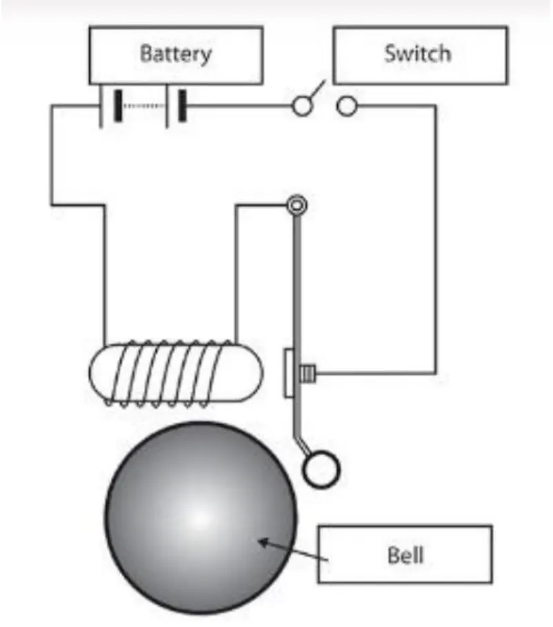
A solenoid converts electrical energy into mechanical work. The tightly wound copper wire creates a magnetic flux when current is passe dthrough it. The housing, made if iron or steel surrounds the coil consentrating the magnetic field generated. The plunger is attracted through the consentration of the magnetic field providing the mechanical force to do the work.
Explanation:
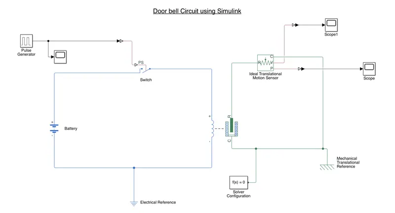
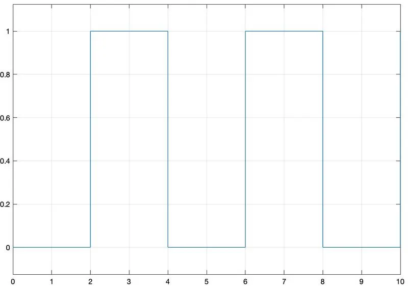
1. To generate the signal required to simulate the doorbell, we use the pulse generator block to get the input signal with a 2 sec step.
2. We need a power source to generate the magnetic field in the solenoid, hence we use the battery block along with tthe electrical reference acting as ground.
3. As the Simulink blocks have outputs in the form of signals, whereas the Simcape blocks have the inputs in the form of energies, we use the Simulink-Ps converter block to conver the outputs from the pulse generator
4. In order to connect the Simulink and Simscape blocks, we give the outputs of the pulse generator to the controlling port of the switch. The output of the switch is connectd to the input of the solenoid. Finally, the output of the solenoid is connected to the battery to finish the input electrical circuit.
5. R is the plunger and C is teh coil of the solenoid. To measure the linear movement of the plunger, we connet it to an Ideal Translational Motion Sensor. The outputs of the motion sensor are connected to a scope to display the values. A Ps-Simulink converter is added to convert them into signal outputs
6. The C ports are connected to a Mechanical Translational Reference to keep a chack on the reference poin on the plunger, so that the displacement of the plunger can be measured.
7. A simulink solver is added tp the circuit to guide MATLAB to use the ode solver to compute the circuit
Results:
Input:
Outputs:
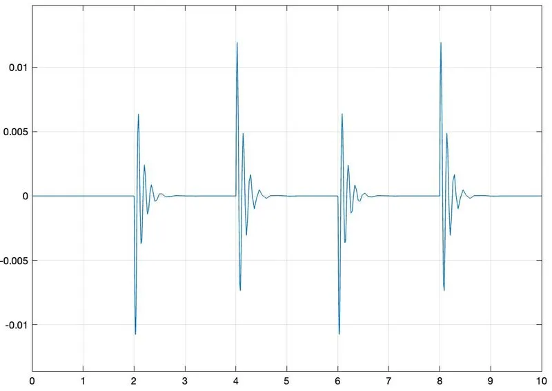
1. Velocity of Plunger
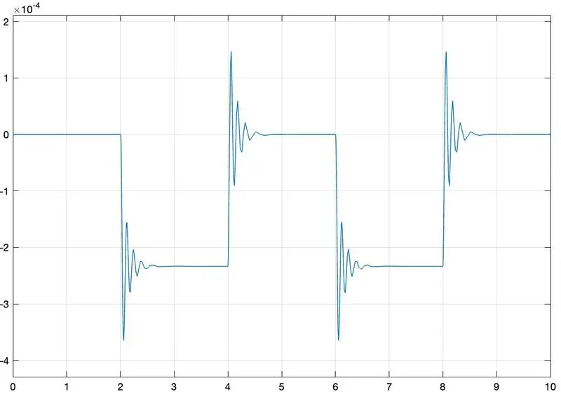
2. Position of Plunger
Study 2: Using a thermistor to sense the temperature of a heater and turn on/off the fan according to cetain conditions
Thermistors ar temperature dependent resistors, that change the resistance when there is a change in temperature. They are very sensitive and react to very minute changes in temperature. They are best used when specific temperature needs to be maintained, upto 50 degrees centigrade.
Explanation:
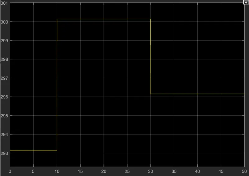
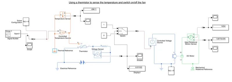
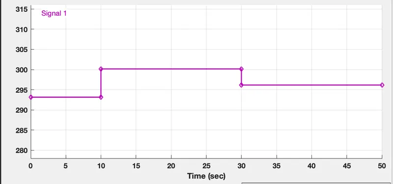
1. We need to input the following conditions: 20 degrees celsius from 0 - 10 seconds; 27 degrees celsius from 10-30 seconds; 23 degrees celsius from 30-50 seconds. We use the signal generator block to create the steps as required. Before we give the inputs, we need to convert the temperature from celsius to kelvin.
2. As the output is in signal form, we need to use the Simulink-PS converter to conver the signal into energy form. We also need to note that the input handling of the converter needs to be changed to filter input and derivative as we are using a controlled temperature source
3. A tempererature sensor and a thermal reference ar eattached to the Conteolled temperature source and the output of the source is connected to the thermistor.
4. The positive terminal of the thermistor is connected to the positive terminal of the battery and the negative terminal is conected through through a resistor and a voltage sensor to the negative terminal of the battery. An electrical reference is placed to complete the circuit.
5. The output of the voltage sensor is connected to a Ps-Simulink converter and the output signal is given to the switch along with a scope and a display blocks.
6. The output of the voltage sensor is given as the threshold cut-off for the switch. In our case, the voltage at 25 degree celsius is 0.01105. thus we feed that as the threshold for the switch to turn on.
7. The output of the switch is connected to a controlled voltage source. The output of the source is connected to the DC motor to simulate the fan. An ideal rotational motion sensor and a Mechanical rotational reference blocks are added to complete the circuit.
8. The outputs for the ideal rotarional motion sensor are connected to a scope through a PS-Simulink converter to measure the displace ment and velocity of the fan.
Results:
1. Input signal provided
2. Output of the Switch