Week -2
AIM: Make a Simulink model of Doorbell using solenoid block
Condition: Switch is closed for 2 seconds and then released
Model of Block:
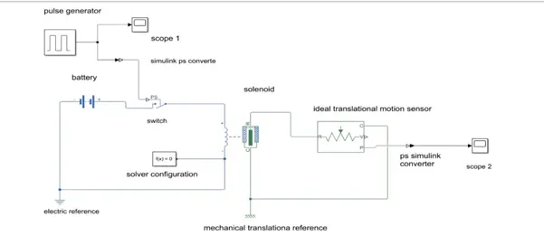
- Battery - A battery is a device that stores chemical energy and converts it to electrical energy. It is made up of three basic components: an anode, a cathode, and an electrolyte. A separator is often used to prevent the anode and cathode from touching, it has got two ports, one port is connected to positive terminal of the switch and the other one is connected to the negative port of the solenoid for the negative terminal and also electric reference.
- Switch – It is an interconnecting device, which helps to flow storage current from battery to solenoid.
- Pulse generator - Pulse generators are electrical test equipment used to generate pulses that are injected into devices under test in order to study the behaviour of these devices.
- Ideal translational motion sensor - The Ideal Translational Motion Sensor block represents a device that converts an across variable measured between two mechanical translational nodes into a control signal proportional to velocity or position. You can specify the initial position (offset) as a block parameter.
- Simulink PS convertor - The Simulink-PS Converter block converts the input Simulink signal into a physical signal. The parameter value controls the unit of the physical signal at the output port of the block
- Scope - The Scope allows you to adjust the amount of time and the range of input values displayed.
- mechanical translational reference - The Mechanical Translational Reference block represents a reference point, or frame, for all mechanical translational ports.
- Electrical reference – this block represents an electrical ground. Electrical conserving ports of all the blocks that are directly connected to ground must be connected to an Electrical Reference block. A model with electrical elements must contain at least one Electrical Reference block.
block diagram of the model
scope
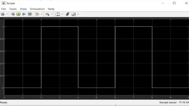
Scope – This scope represents the simulation time as well as amplitude, overall period of time, maximum % of period of pulse width and also phase delay therefore 0 to 2 switch is in off condition and then 2 to 4 is in on condition.
Scope 1
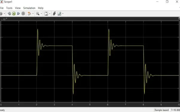
This scope shows actually time of the bell ring for 2 sec off and 2sec is on.
Pulse generator Parameter Block
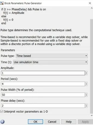
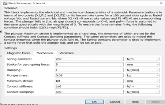
Solenoid parameter
Results : for the above results the given condition has been achieved and successfully executed.
AIM: Thermistor to sense the temperature of a heater & turn on or turn off the fan
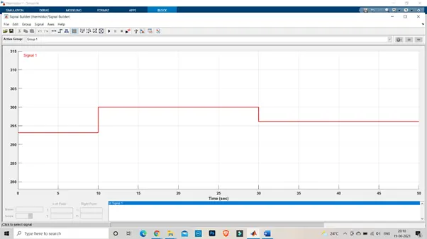
Given conditions: Temperature source: 20 °C from 0 to 10 seconds, 27 °C from 10 to 30 seconds, 23 °C from 30 to 50 seconds
Fan conditions: ON if the temperature above 25 °C, OFF otherwise
Thermistor: an electrical resistor whose resistance is greatly reduced by heating, used for measurement and control.
Name of the blocks
- signal builder
- simulation physical source
- controlled temperature source
- thermistor
- battery
- Voltage Sensor
- Resistor
- PS- Simulink Converter
- Switch
- 3 scopes
- Electrical and thermal reference
- Ps- Simulink converter
Block diagram
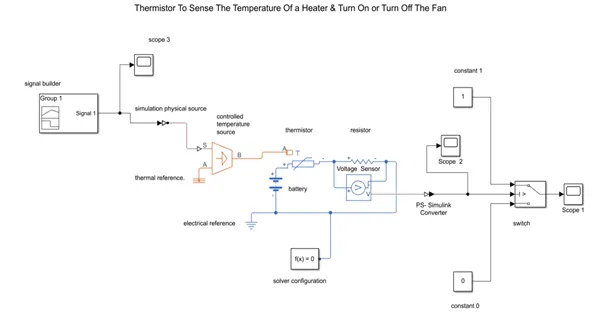
color represent:
orange – sensor system
blue – electrical system
black – Simulink system
model explanation
- Signal Builder - This block allows you to create interchangeable groups of piecewise linear signalsources and use them in a model. In the Signal Builder window, create signals and define the output waveforms.
- Controlled temperature source - this block represents an ideal source of thermal energy that is powerful enough to maintain specified temperature difference across the source regardless of the heat flow consumed by the system.
- Thermistor – This type of resistor whose resistance is dependent on temperature, more so than is standard resistors. This block represents an NTC thermistor using the B- parameter equation. NTC – Negative Temperature Co- efficient
- Resistor - The resistor block models a linear resistor, described with the following equation. V=I*R
Where, V- voltage,
I – Current,
R – Resistance,
- Voltage sensor - it is an ideal voltage sensor, that is, a device that converts voltage measured between two points of an electrical circuit into a physical signal proportional to the voltage.
- Voltage source – the voltage source block implements a voltage source with DC,AC, and noise components.
- Electrical reference – this block is purely connected to the electrical ground, electrical conserving ports of all the blocks that are directly connected to ground must be connected to an electrical reference block. A model with electrical elements must contain at least one electrical reference block.
signal builder parameters:
Scopes
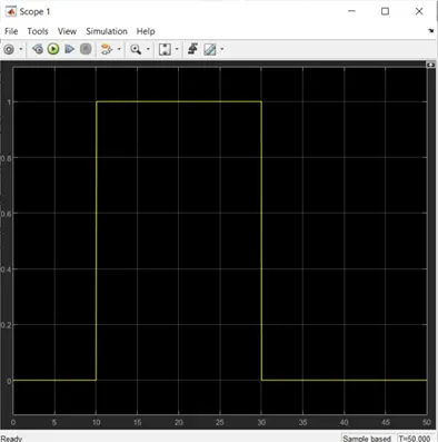
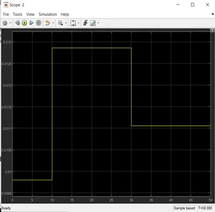
Scope Outputs:
For 0-10 sec fan is in off condition, because temperature is 293k which is below 298k. after 10sec temperature goes to 300k, so fan will turn ON, because temperature exceeds 298k. after 30sec fan will turn off because temperature goes to 296k which is below 298k.
Results : for the above results the given condition has been achieved and successfully executed.