Project
AIM :
To Determine and analyse about ATV (All Terrain Vehicle) Powered by bajaj through MATLAB simulink.
THEORY :
All terrain vehicle :
- An all-terrain vehicle (ATV) is defined as a motorized off-highway vehicle designed to travel on four low-pressure or non-pneumatic tires, having a seat designed to be straddled by the operator and handlebars for steering control. Similarly, riders must also consider the various ATV sizes. They are subdivided into two types as designated by the manufacurer.
- Type 1 ATVs are intented by the manufacturer for use by a single operator and no passenger where the type 2 ATVs are manufactured for the operator and a passenger and are equipped with a designed seating position behind the operator.
- The continously variable design ensures the ATV or UTV is always in the 'right' gear and the engine RPM is the heart of the powerband to deliver optimum power to the ground at any speed and in every application.
Continously variable transmission :
- A continuously variable transmission (CVT) is an automatic transmission that can change seamlessly through a continuous range of gear ratios. This contrasts with other transmissions that provide a limited number of gear ratios in fixed steps. The flexibility of a CVT with suitable control may allow the engine to operate at a constant RPM while the vehicle moves at varying speeds.
- CVTs are used in automobiles, tractors, motor scooters, snowmobiles, and earthmoving equipment.
- The most common type of CVT uses two pulleys connected by a belt or chain, however, several other designs have also been used at times.
- Decades back it was thought that a 3 gear or 4 gear system is sufficient for a vehicles transmission.In fact many early automatics had only two speeds but now the gears 8 to 10 gears are present.
- It is easy to optimize engine speed in various drive conditions. Lower gears can provide better acceleration whereas higher ones can increase efficiency thereby fuel economy.
Signal builder :
- It is a signal builder block which is used to build signal as per the requirement. here it is used as a transmission for the vehicle.
Generic engine :
- It is general internal combustion engine that includes spark ignition and diesel. This is used to run the model and to transmit the power.
Engine sensor :
- This helps in sensing the engine RPM, velocity and angular displacement acting on the engine.
Vehicle body :
- It is a block for body mass, aerodynamic drag, road incline and weight distribution between the axles due to the accletarion and road profile.
CASE STUDY 1:
CASE 1 : Simulation of Bajaj ATV model with CVT
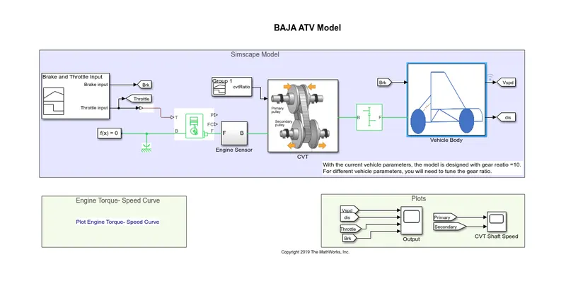
Inputs to the model and the blocks :
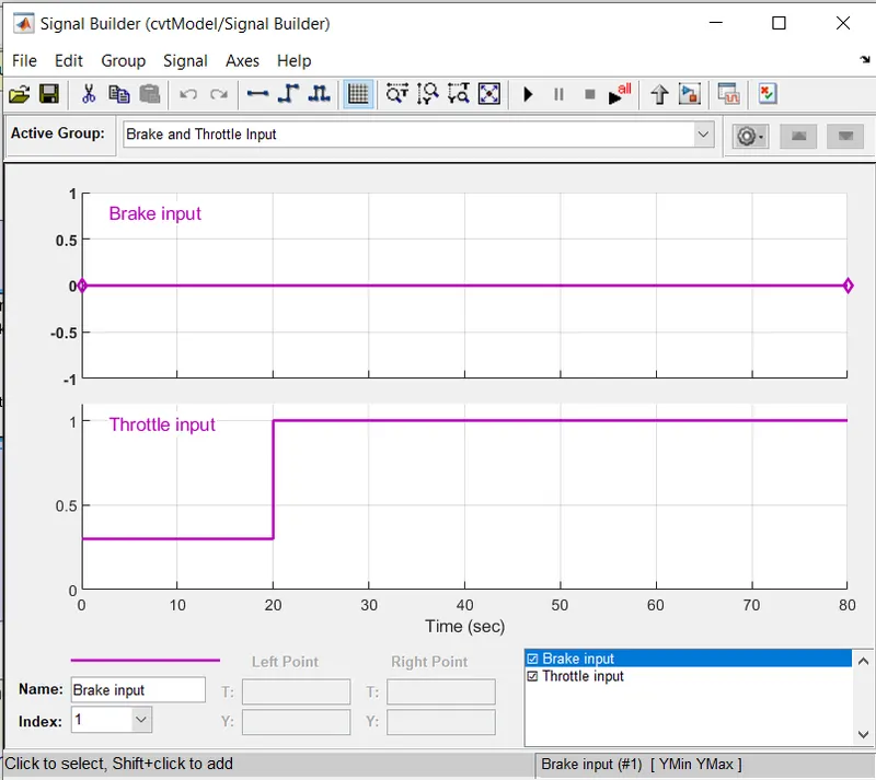
There are two points provided using signal builder one is brake input given a zero value and the other is throttle input which the input is 0.30 for 20 seconds and is increased to 1 and remains same for 80 seconds these are given to generic engine block.
Continous variable transmission :
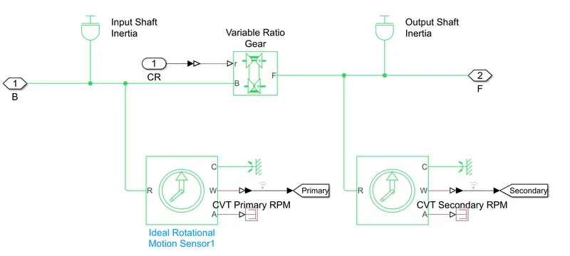
- There are two pulleys a primary which is driving and second which is driven.
- These have an input and output shaft inertia respectively.
- The variable ratio gear block provides the different gear ratios( represents multiple gear of CVT)
- The angular velocity of the two pulleys is tracked using ideal rotational sensors.
- The input to the CVT is defined using a signal builder block.
Vehicle body :
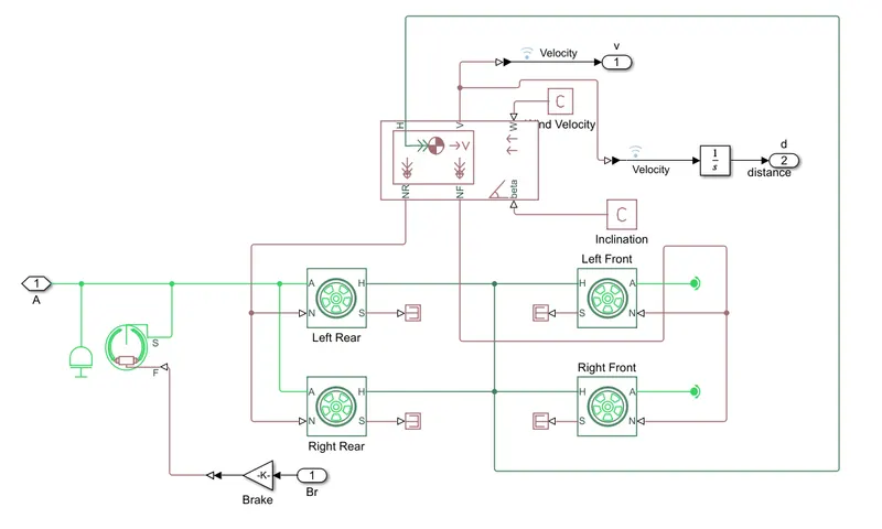
- The vehicle subsystem accounts for the forces acting on the body.
- It has to produce tractive effort to overcome forces due to drag, rolling resistance, hill climb and also acceleration.
- In a subsystem a double shoe brake is applied to the rear wheels. Two of these are kept at both ends to prevent action of unbalanced forces.
RESULTS AND OBSERVATION :
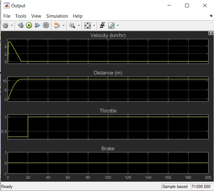
The above figure shows the change in velocity applied, throttle and brake input.
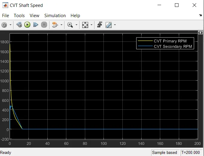
In the above figure we can observe the primary cvt and secondary RPM.
We can change so many parameters like torque, velocity, brake input, throttle, mass of the body, inertia of the body and so on.
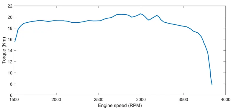
This gives the relation between speed and torque for the terrain vehicle at various inputs given to it.
CASE STUDY 2 :
case 2 : Simulation of Bajaj ATV model with cvt and dashboard
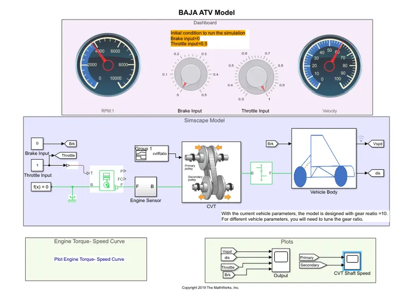
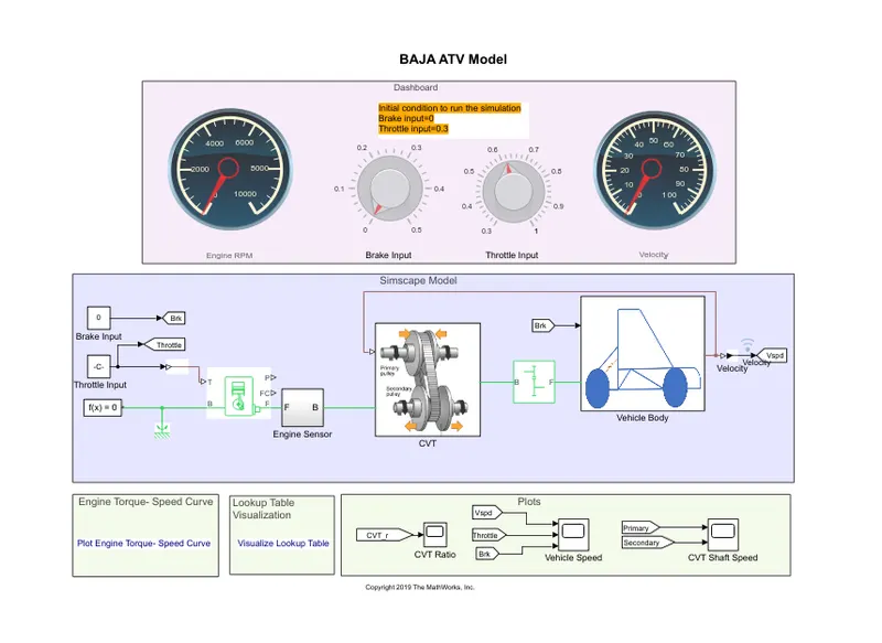
- The Gauges in the display show the amount of brake input and the throttle input to the system. There will be variation in the velocity when the brake input in applied. This describes the behavior of the vehicle in different terrain.
- The knobs above can be used to control the brake and throttle input in real time.
The above shows the Engine torque vs speed
RESULTS AND OBSERVATION :
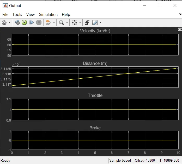
The above shows vehicle speed curve.
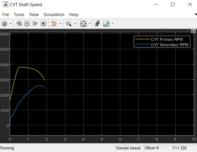
The above plot shows the CVT shaft speed.
CASE 3 :
case 3 : Simulation of bajaj ATV model with a look up table - The difference is feedback
- A look up table is a array od data that maps input values to output values. This is done to get the approxmate value of the mathe,atical function. When a set of input values are known a look up yield an output value corresponding to each input from a table of values the look up table does not explicity define the input values.
- Interpolation is the process for estimating the values that lie between knoown data points.
- Extrapolation is the process for estimating the values that lie beyond the range of known data points.
- Rounding is a process for approximating value by altering its digits according to a known rule.
RESULTS AND OBSERVATION :
Engine torque vs speed :
CVT shaft speed :
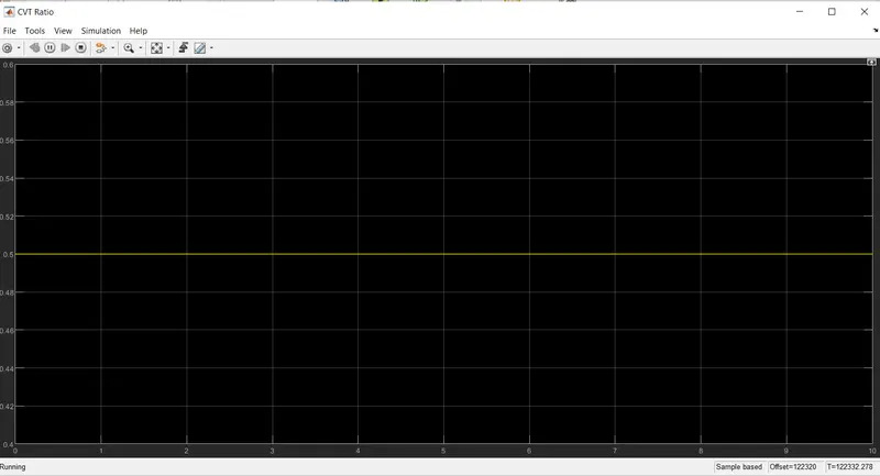
- For starting the vehicle needs a high torque hence a higher value of CVT
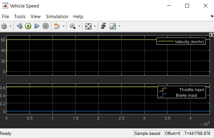
Vehicle speed curve :
CVT ratio :
CASE 4 :
Case 4 simuation of bajab ATV model with CVT and dashboard :
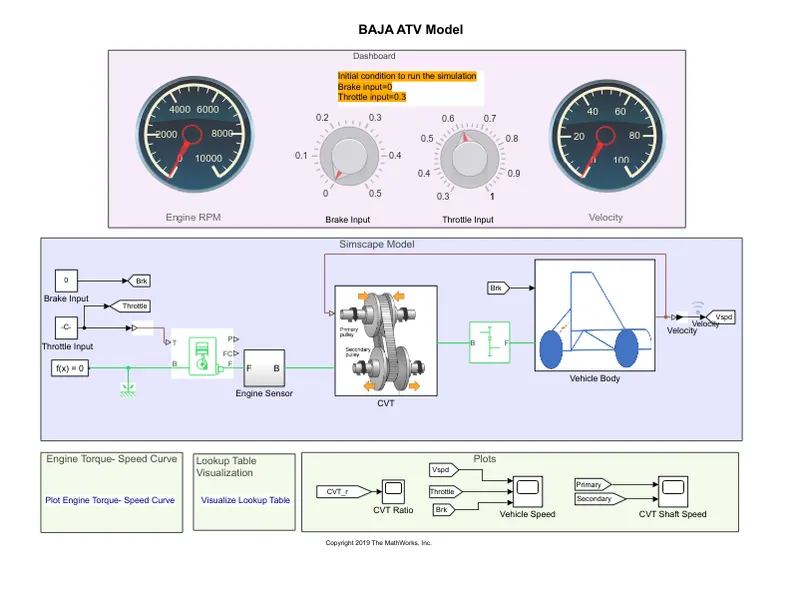
- With the help of knob it is possible to control the throttle and brake inputs.
- A lookup table is used to establish a relationship between vehicle speed and CVT.
- The initial input for throttle is 0.3 and for brake is 0.
RESULTS AND OBSERVATION :
Engine torque vs speed :
CVT ratio :
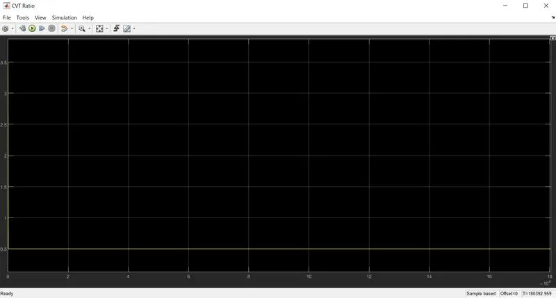
The input value of throttle is set at 0.3 so there is a gradual decline in CVT ratio but a steep fall at start itself it can been seen in the scope.
Vehicle speed curve :
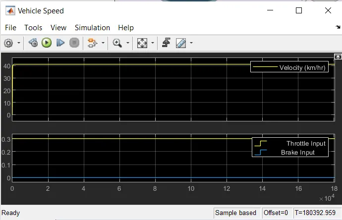
When there is a fall in speed there is a increase in brake input.
CVT shaft speed :
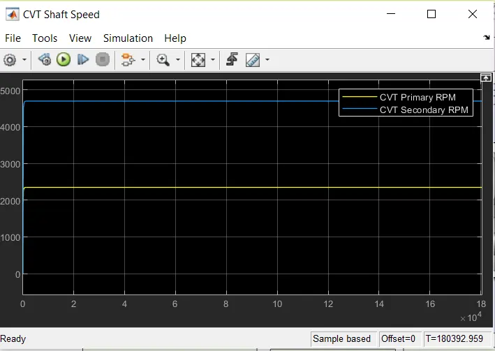
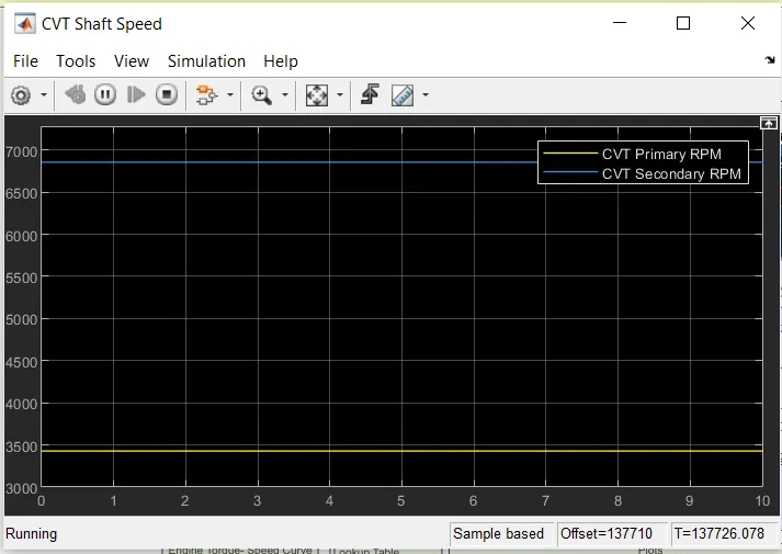
When throttle value increases the speed increases which is met by a increase in secondary rpm and during uniform speed the CVT ratio does not change which is seen via the primary and secondary rpm remain constant during this periods.
LEARNING OUTCOMES AND INTERFERENCE :
- The quality of output is based on the type of input.
- It is better to vary the values in real time than a signal builder.
- Lookup table makes the curves smoother. if the look up table does not explicitly define the values. Simulink helps by estimating the output values by interpolation, extrapolation and rounding giving better quality results.
- It is always good to get the desired output with the feed back.
- Understanding of working of a CVT.
- As a throttle input increases there happens a increase in speed but thee cvt ratio fails, when there is an increase in brake input the speed falls but there will be increase in CVT ratio.