Week 14 challenge
Assemble and apply GD&T to the butterfly valve assembly drawing
AIM:
The aim of this project is to model a butterfly valve and to apply GD&T to the different parts of the butterfly valve and the assembly.
INTRODUCTION
Butterfly valves are a family of quarter-turn rotational motion valves that are used in pipelines to shut-off flow. It is often said that butterfly valves can be used to regulate the flow. However, we do not recommend doing this, as it can damage the valve disk and have a negative effect on the sealing properties. They are used in a wide variety of process media and industries especially in water supply, collection, and distribution, as well as pumping stations, and have a broad range of use cases especially in flow isolation. A couple of their key advantages over other valve families are their simple construction and compactness, resulting in the end products being of lighter weights and lower cost and with smaller installation footprints and faster actuation speeds.
Butterfly valve parts
Below are the major butterfly valve components:
- Valve Body
The valve body fits between the pipe flanges - the most common end connection types being flanged, double lug, and wafer types.
- Disc
Attached to the valve body is the disc that functions as a gate that stops or throttles fluid flow; it can be considered equivalent to a gate in a gate valve, or a ball in a ball valve. The disc is typically bored to receive the stem, or shaft. There are many variations in disc design, orientation, and material in order to improve flow, sealing, and/or operating torque. For example, Hawle’s 9881k double eccentric disc is designed to reduce seal wear and “scuffing” as well as operating torque requirements.
- Seat
Lining the internal valve body is a strong elastomer or metal anti-leak seal that secures the disc in place in the closed position in order to achieve complete shutoff. The 9881k series’ stainless steel weld filled and microfinished integral body seat ensures a corrosion and erosion resistant seat face. With this special type of seat design, it is possible to manufacture the valve drop tight according to EN12266 –A requirements.
- Stem
The valve shaft, often also referred to as the stem, is the component that connects the disc to the actuation mechanism and transmits the torque through itself.
- Seals
Seals are present at multiple interfaces within the valve to either ensure a tight seal during operation or to isolate the process media from the valve’s internal components for a more flexible and cost-efficient design.
Sealing on seat face is ensured by a continuous T-profile resilient sealing ring which is held on the periphery of the disc by a retaining ring, preventing the sealing ring from rolling out. In the closed position, the sealing ring is pressed against the seat face, providing a tight seal on both the upstream and downstream ends. In the open position, the sealing ring is completely unstressed due to the double eccentric disc design.
By eliminating interaction between the process media and the stem/shaft, the multiple O-ring shaft sealing system ensures a maintenance-free sealing for the entire life span of the valve. Besides, there are smaller more common components such as the bushings, bearings, and fasteners that are part of most other valve constructions as well. Details on some of the components on the actuation end, such as the handle, lever, gearbox, and handwheel will be covered in the actuation section.
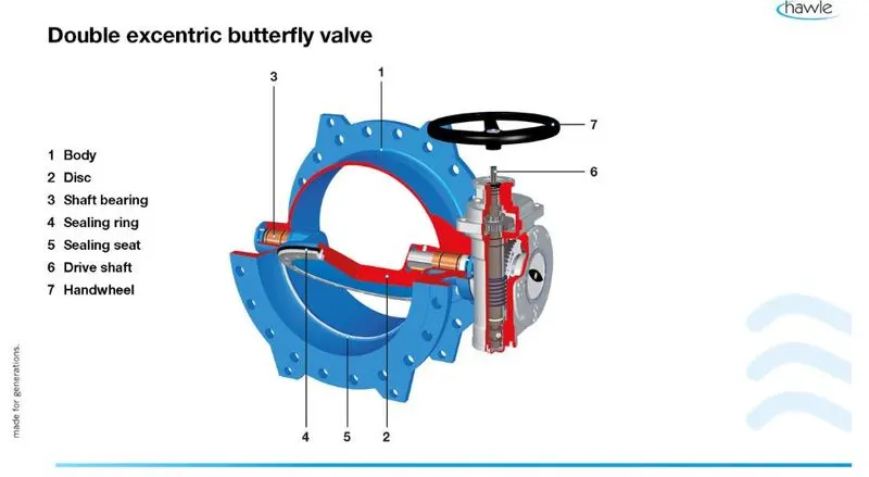
Butterfly valve: working principle
The construction of a butterfly valve is relatively simple, with the rotation of the valve disc controlling the fluid flow. In the closed position, the disc blocks the valve bore while in the open position, the disc is oriented perpendicular to the flow direction to allow flow. Butterfly valves generally provide bi-directional flow and shutoff capability. However, they are not full-bore, which renders them unsuitable for pigging or swabbing. The body material is ductile iron with an epoxy powder coat on both internal and external surfaces. The valves are typically operated by handwheels, gears, or actuators, or a combination thereof, according to the specific application requirement and technical specifications. We will be discussing the actuation methods later in the article.
DESCRIPTION OF BUTTERFLY VALVE:The different parts of the Butterfly valve are as follows:
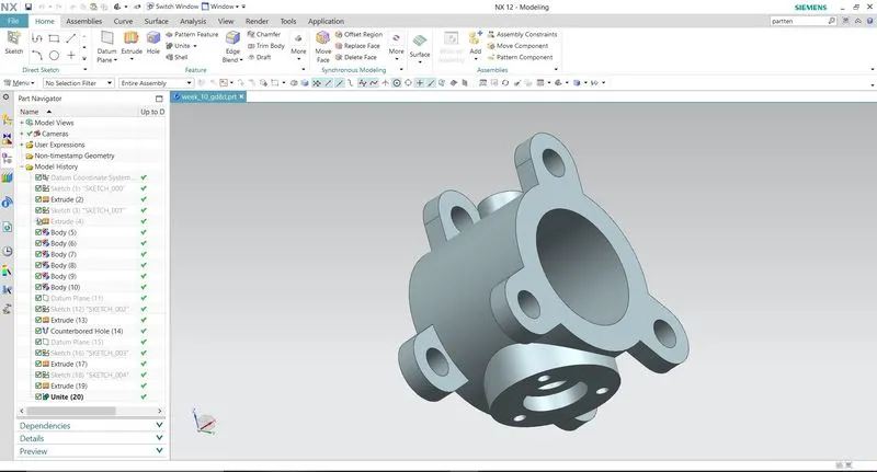
1.BODY OF BUTTERFLY VALVE:
1.Initially, the sketch for the body of the butterfly valve is drawn using the circle tool in NX software.
2.After extruding the sketch which is drawn,the ears of the Butterfly valve is drawn and then it is copied on both sides of the cyclindrical portion.
3.Now, the datum plane option is used to create cyclidrical portion and the counter bore option is used to provide a counter bore to the part with the specified dimensions.
4.Finally, the hole is provided for the mounting of the body and it is saved in the required folder.
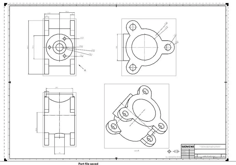
FOR THIS CAD MODEL DRAFTING IS CREATED AN SHOWN BELOW
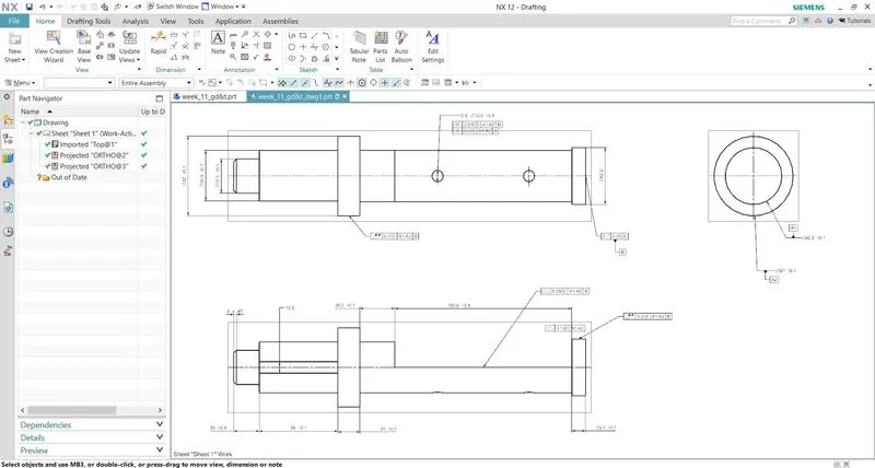
2.SHAFT:
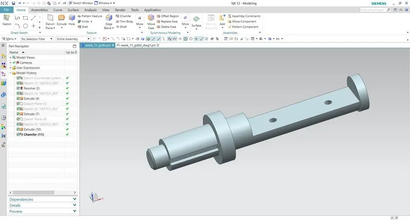
1.The 2D drawing given in the figure is used to convert the Sketch into 3D model with different operations.
2.The revolve option is used to create the shaft by rotating it through 360°.
3.Now the extrude option(Subtract) is used to provide the recess in the front and rear portion of the shaft.
4.Finally,the two holes of 12.5mm diameter is provided in the rear recess portion of the shaft and the part is saved in the required folder.
FOR THIS CAD MODEL DRAFTING IS CREATED AN SHOWN BELOW
3. Retainer
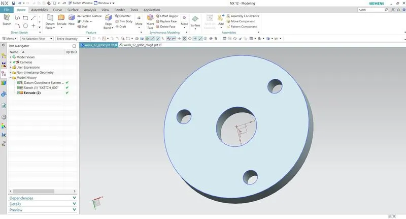
The retainer is a specially shaped-washer that fits over the top of the valve spring. The keepers, or locks, fit into the valve stem grooves, holding the retainer and spring in place.
A CAD MODEL IS CREATED FOR THIS MODEL AND SHOWN BELOW
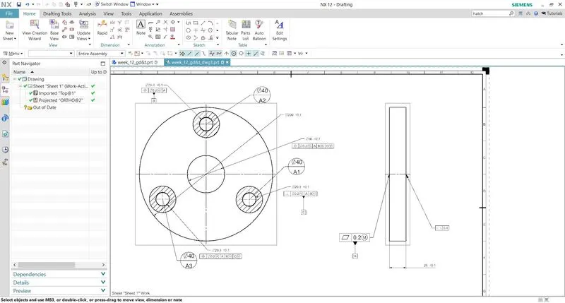
DRAWING OF RETAINER:
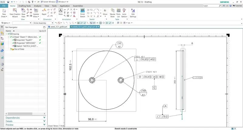
1. After the modeling, the part is taken to the drafting portion where the three datums A, B, C are applied.
2. Datum target areas A1, A2, and A3 (Primary datum-A) are applied to one side of the Retainer which comes in contact with the upper portion of the body.
3. Datum-B is applied to one of the holes of the retainer where the bolt is inserted.
4. Datum-C is applied to the other hole of the retainer.
5. Finally, the other tolerances like Perpendicularity, position and profile of a surface are applied to the other holes and the surfceof the retainer, the drawing is saved in the required folder.
4. Disc
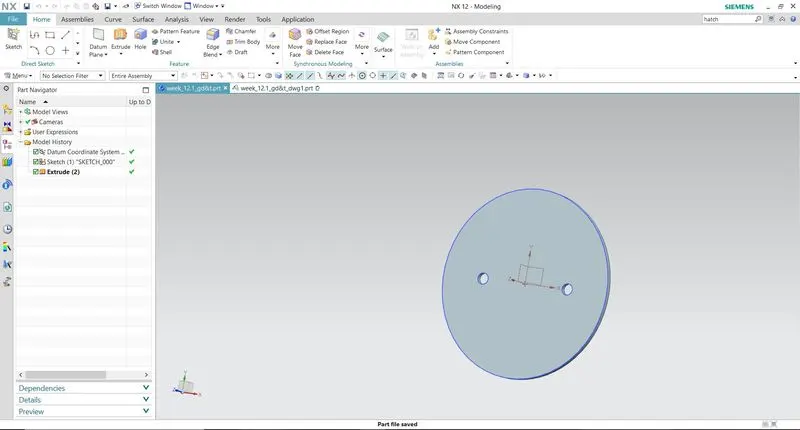
The flow closure member of a butterfly valve is the disk. The disk is the equivalent of a plug in a plug valve, gate in a gate valve or a ball in a ball valve. Rotating the disk one-quarter turn or 90 Degrees opens and closes the butterfly valve.
A CAD MODEL IS CREATED FOR THIS MODEL AND SHOWN BELOW
- After the modeling, the part is taken to the drafting portion where the three datums A, B, C are applied.
- Datum target areas A1, A2, A3(Primary datum-A) are applied to one side of the Retainer which comes in contact with the upper portion of the body.
- Datum-B is applied to one of the holes of the retainer where the bolt is inserted.
- Datum-C is applied to the other hole of the retainer.
- Finally, the other tolerances like Perpendicularity, position, the profile of a surface are applied to the other holes and the surface of the retainer, the drawing is saved in the required folder.
5. Lever
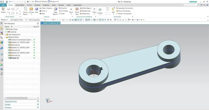
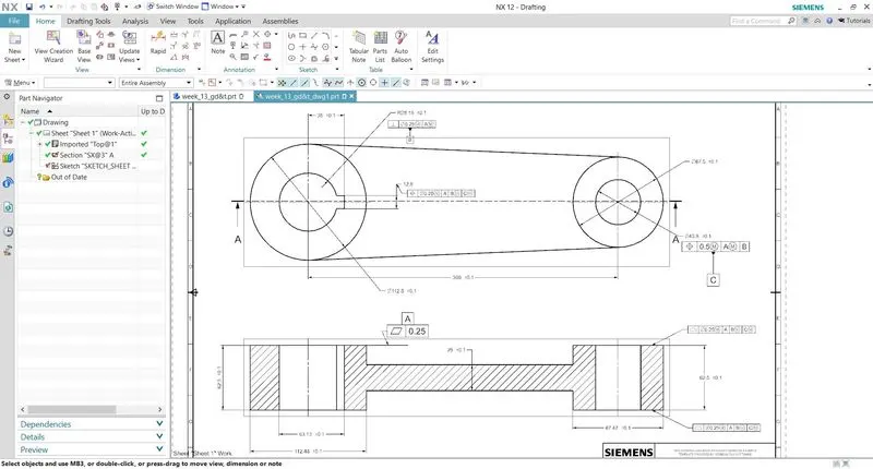
A lever is a handle that is used to rotate to regulate the flow. It is attached to the shaft with the help of a key to fixing it in position concerning it. So when it is rotated, the shaft rotates which in turn rotates the disc and regulates the flow inside the pipe. It is created using simple features like extrude in NX after the proper base sketch is created. For the application of GD&T on the lever, a section view is also created to show how different datums are defined and tolerances are provided. Position tolerance is applied to the proper holes after the perpendicular tolerance is applied to the first hole. To control the key slot, small tolerance is applied to the width of it. Profile tolerances are provided to the surfaces which come to contact with other parts as per the requirement.
Drafting Methodology
- After the design of the lever, the drafting of the lever is done for applying the GD&T.
- Three datums A, B, C are applied to the part.
- A datum- To the bottom surface of the lever that comes in contact with the other surface.
- B datum- It is applied to the hole where the bolt comes in contact.
- C datum- It is applied to the other hole to completely constraint the part.
- Finally, all the other tolerances like position, Flatness, Profile of a surface are applied to the part.
6. Nut
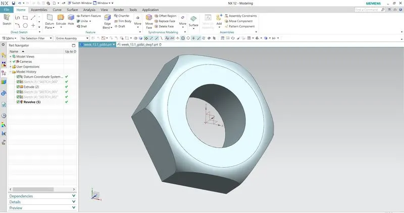
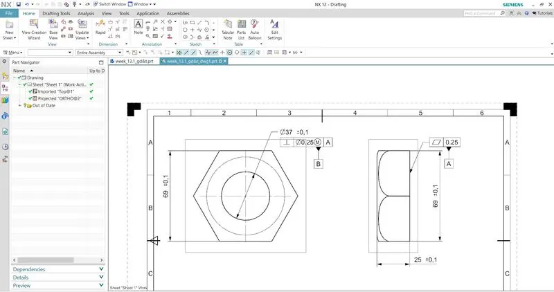
It is the last part that helps to fix the lever in position with the stem. It allows to keep it in position or to disassemble whenever required. It is created using simple extrude and revolve features in NX. To apply GD&T for this nut, the primary datum is defined on the surface which comes in contact with the lever. Perpendicular tolerance is applied to the hole or the thread and is defined as datum B. Size tolerance is also applied to the thickness of the nut.
Drafting Methodology
- Datum A is given to the bottom surface of Nut which is going to come in contact with the Lever surface.
- Datum B is given to the Hole.
- Finally, other tolerances are given to the surfaces and features of Nut.
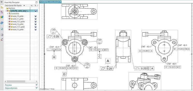
Assembly
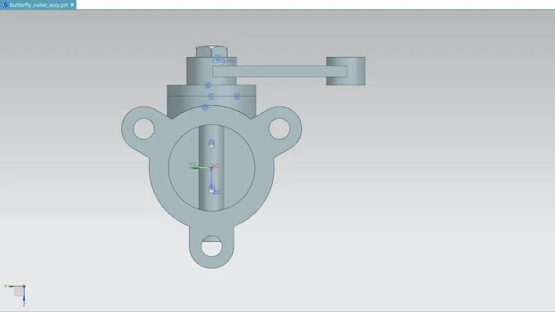
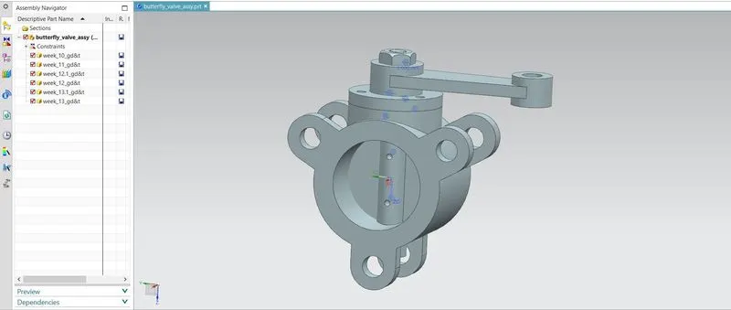
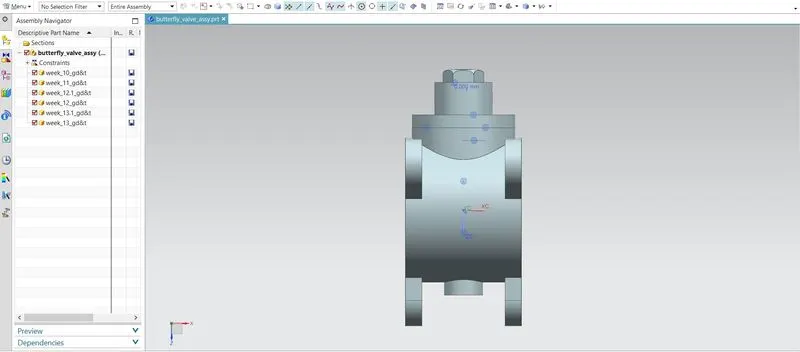
After the design, all the models should assemble with appropriate constraints. The assembly is created by first placing the body in position and mating other parts to it with the application of different joints provided in NX. First, the shaft and disc are joined together with the screws in place to create a sub-assembly which is then joined to the body in position. The retainer plate is then mated with the body and screws are used to fix them. After that, the lever is mated to the shaft in a position that is then fixed after the nut is mated with the shaft.
Drafting Methodology
- Datum target area A1,A2 and A3 is given to the ears of the butterfly valve.
- Datum target area A2 and A3 is given with perpendicular tolerance and Position tolerance respectively.
- Sub datum D is given to the third ear.
- Finally, other tolerances are given to the surfaces and features of the Butterfly Valve.
Conclusion
In this project, a butterfly valve is designed and assembled in parametric CAD software, Siemens NX. GD&T according to ASME Y14.5 is applied at every stage of the part design process in order to make communication with the manufacturers effective and efficient. Hence, a design process in a real industrial manner is followed in this design of the butterfly valve understanding the design process more with the application of GD&T with industrial standards.