Week 14 challenge
Final Project Report: Butterfly Valve Assembly in NX CAD
1. Introduction
The objective of this project is to design, model, and assemble a butterfly valve in NX CAD by creating individual components, applying GD&T symbols to each drawing sheet, and finally assembling all components using the Assembly Workbench. This report covers the design and modeling process of all parts, including the shaft, Disc Plate , Retainer , Butterfly Valve Body , Nut , Lever Assembly of All Components Each part was modeled based on industrial design standards and functional accuracy for a complete and operational Butterfly Valve model
2. Software Used
* Siemens NX CAD
* Part Modeling
* Drafting Module
* Assembly Workbench
* GD&T (Geometric Dimensioning and Tolerancing) Tools
3. Component Modeling
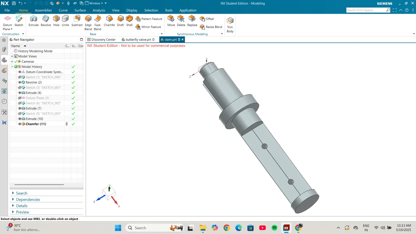
3.1 Shaft
The shaft was designed to transmit torque from the lever to the disc, allowing flow regulation. It includes bearing seats, keyways, and GD&T for runout and concentricity.
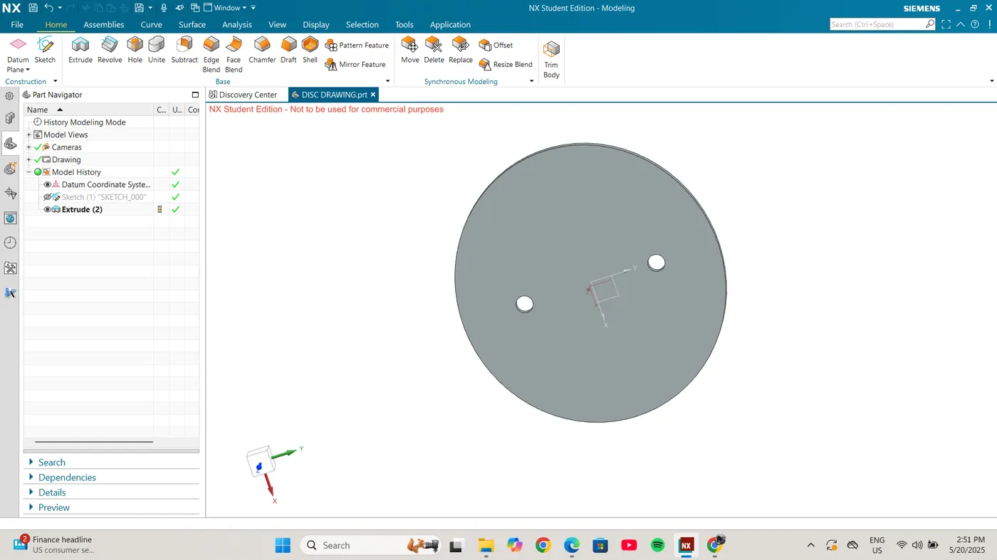
3.2 Disc Plate
The disc plate acts as the main flow control element of the valve. It rotates within the body and is attached to the shaft.
3.3 Retainer
The retainer holds the disc in place and helps maintain internal alignment. It was designed with slots for fasteners and optimized thickness.
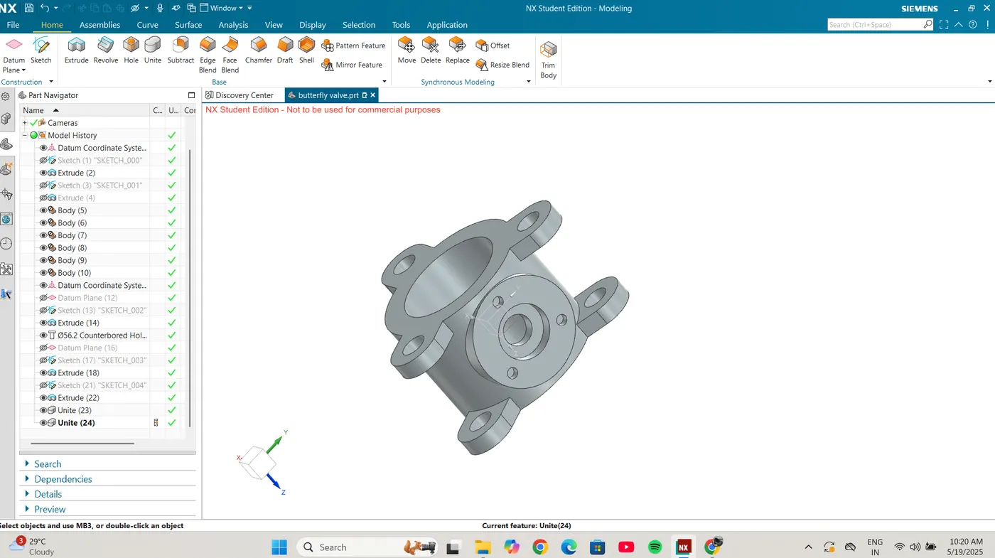
3.4 Butterfly Valve Body
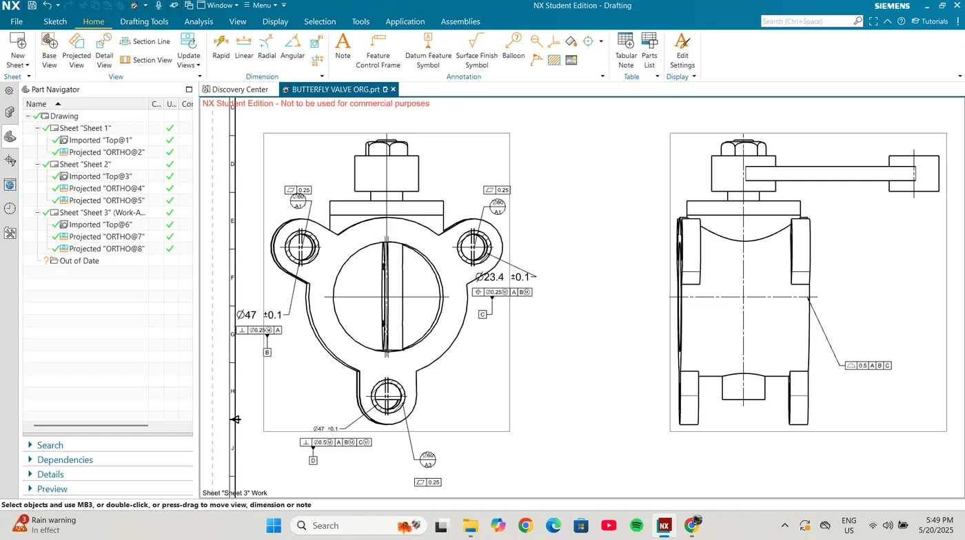
The main body houses the disc and provides the passage for fluid flow. The body includes mounting flanges, bolt holes, and a bore for shaft insertion.
3.5 Nut
The nut is a fastening component used for securing the shaft and other parts within the valve body. It was modeled with standard thread profiles and tolerance callouts.
3.6 Lever
The lever is connected to the top of the shaft and is used to manually operate the valve. It includes a grip handle and features for mechanical locking.
4. Assembly
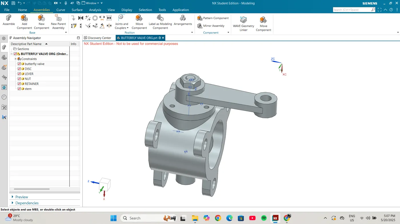
All the components were assembled in the NX Assembly Workbench using appropriate constraints like concentric, axial, and face mating. Proper alignments and clearances were maintained to ensure the operability of the valve. Key Assembly Features:
*The shaft was inserted into the disc and body.
* The retainer secured the disc inside the valve body.
* The nut fastened the shaft to hold the disc in position.
* The lever was placed on top of the shaft for operation.
5. Application of GD&T
Each component and the final assembly were dimensioned and toleranced according to ASME Y14.5M-1994 standards. Important GD&T symbols applied include:
* Flatness for flanges,
* Concentricity for shafts and bores,
* Perpendicularity for bolt holes,
* Position Tolerance for mounting holes
* Runout for rotating parts GD&T improves the clarity of functional requirements and facilitates manufacturing and inspection processes.
6. Conclusion This project demonstrates a comprehensive understanding of 3D part modeling, mechanical assembly, and engineering drawing creation using NX CAD. The final assembly accurately represents a functional butterfly valve with proper fit, form, and tolerance.