Week 14 challenge
BUTTERFLY VALVE ASSEMBLY AND APPLYING GD&T TO THE ASSEMBLY
Aim:
To create the Butterfly Valve part and assemble the part and also apply the GD&T with Drawing sheet
Objectives:
- The Main objective is to create and assemble the various component of butterfly valve using simens NX CAD
- Assemble all the individual parts of the butterfly
- Understand various GD&T symbols and how they apply to butterfly valve assemblies.
Introduction:
- Simens NX CAD:
NX, formerly known as "unigraphics", is a leading high-end CAD/CAM/CAE company owned by Siemens Digital Industries Software since 2007. In 2000, Unigraphics SDRC acquired his I-DEAS and he began to integrate aspects of both software packages into one product, which became Unigraphics NX or NX.
It is used in particular for:
- Design (parametric and direct solid/surface modeling)
- Engineering analysis (static, dynamic, electromagnetic, thermal using finite element method, and fluid flow using finite volume method).
- Create a finished design using the included editing module.
- Butterfly Valve:
A butterfly valve is a type of quarter-turn, rotary-acting valve used to block flow in pipelines. It is often said that butterfly valves can be used to regulate flow. However, it is not recommended to do this as it can damage the valve disc and impair its sealing properties.
- GD&T:
Geometric Dimensioning and Tolerancing (GD&T) is a system for defining and communicating engineering tolerances and relationships. It uses a symbolic language for engineering drawings and computer-generated 3D solid models that explicitly describe the nominal geometry and its permissible variations. This tells manufacturing personnel and machines what level of accuracy and precision is required for each controlled function of the part. GD&T is used to define the nominal (theoretically perfect) shape of a part or assembly, define the allowable variation in shape and possible size of individual features, and define the allowable variation between features .
Component Of Butterfly Valve:
- Body
- Shaft/Stem
- Retainer
- Disc Plate
- Lever
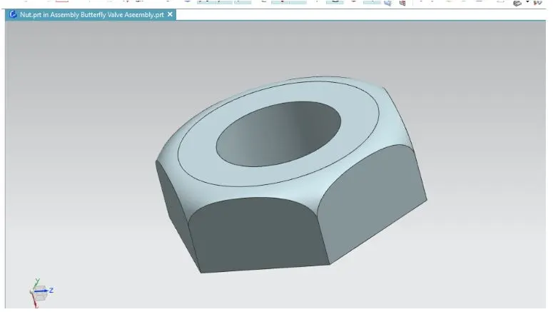
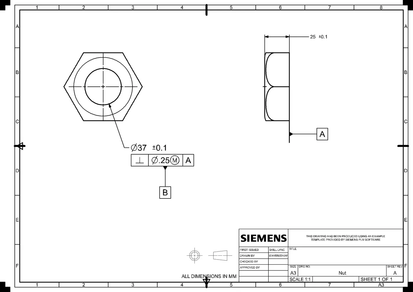
- Nut
Initially the modelling of all these parts were done and GD&T was applied to the individual parts. Then they are assembled together by providing the required assembly constraints and GD&T is applied to the assembly. The software used is Siemens NX.
Butterfly Valve Body.
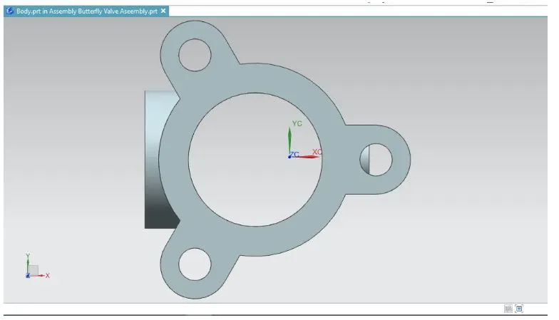
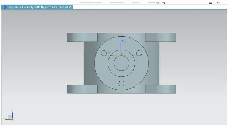
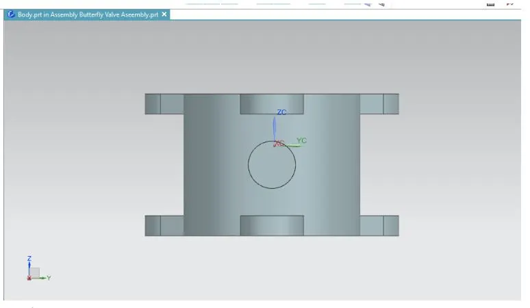
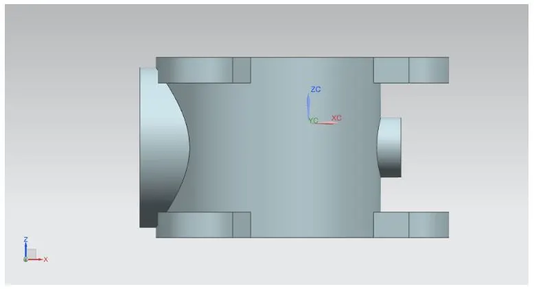
Different Views of Butterfly Valve body
Top View
Left Side view
Right Side View
Front View
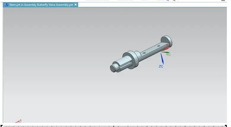
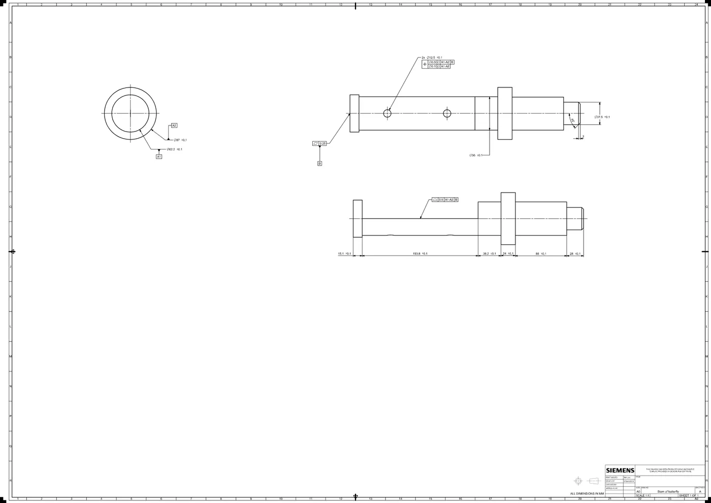
Stem/ Shaft
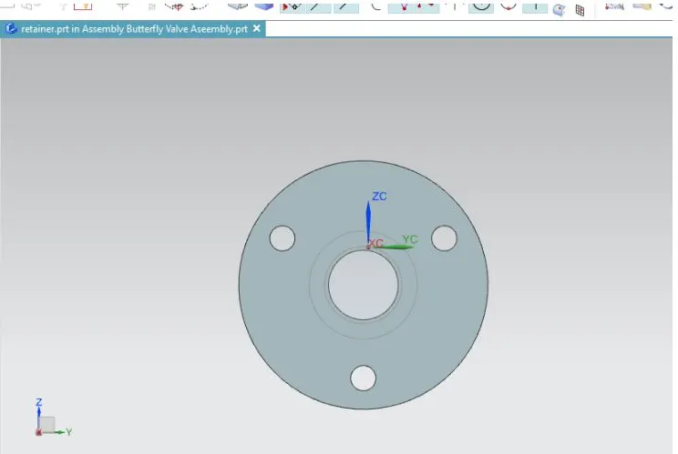
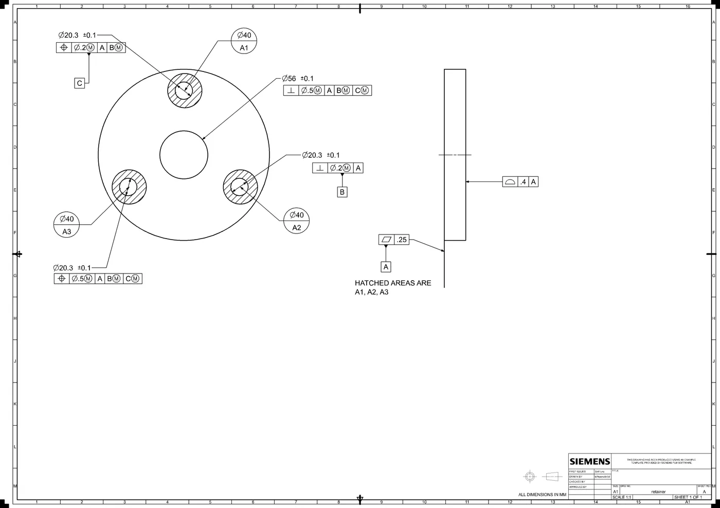
Retainer
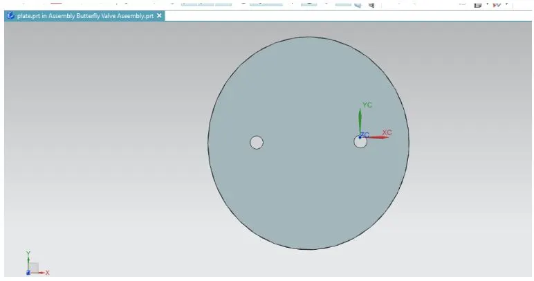
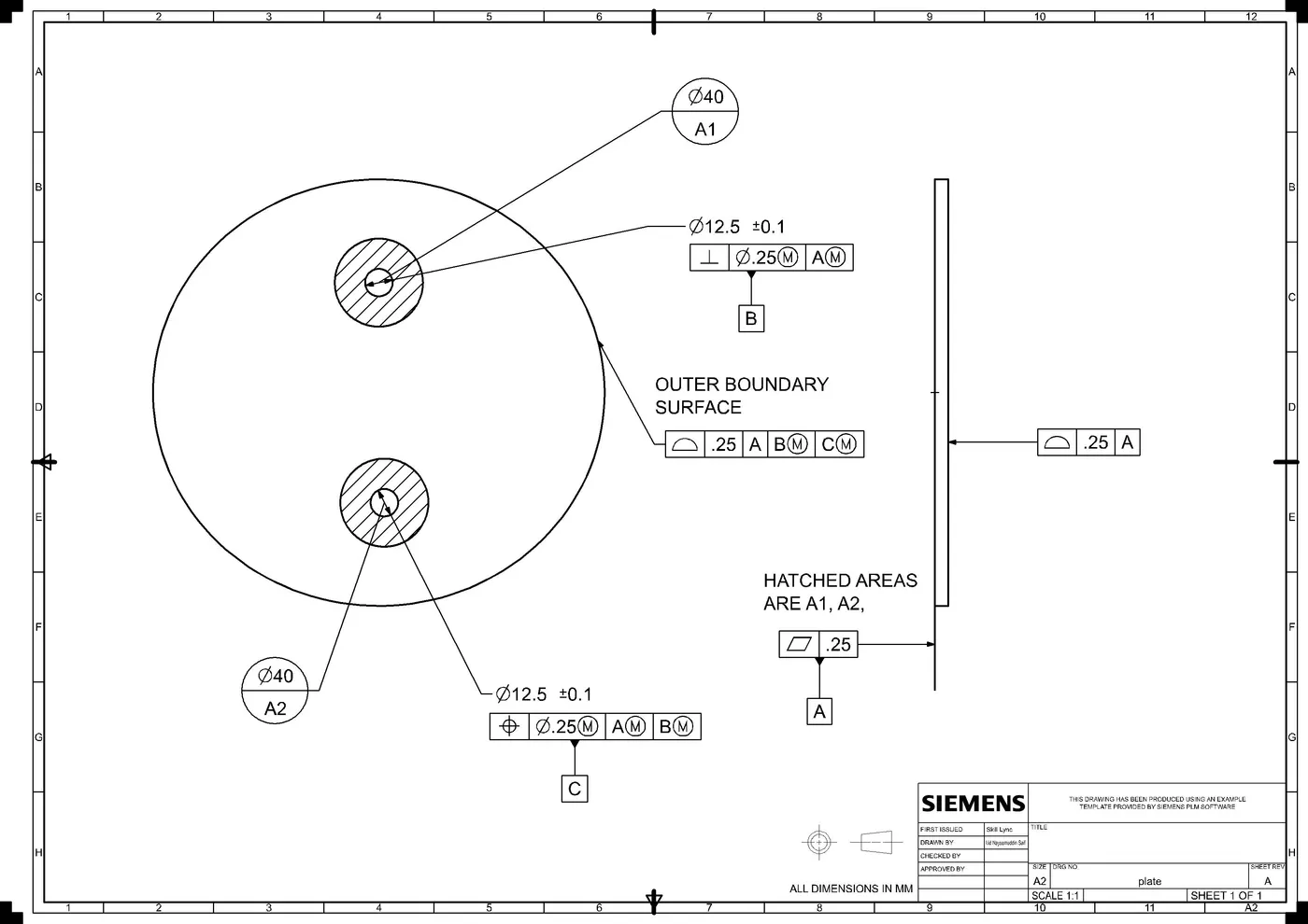
Disc Plate
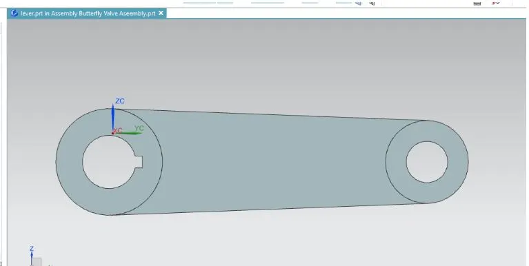
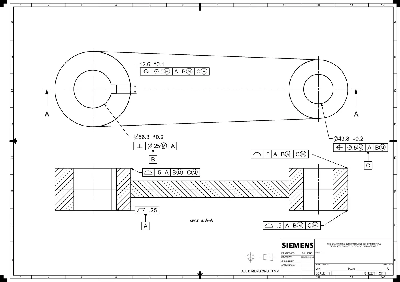
Lever
Nut
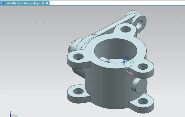
Butterfly Valve Assembly
Assembly
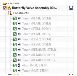
The initial step for assembling the parts is to create an assembly file in the folder where all the part files are saved. Then each part is introduced into the workbench using Add Component command. Then the parts are moved to the respective positions using Move Component command and proper constraints are given for assembling the parts with each other.
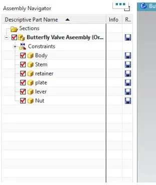
Assembly Constraints
Different views of Butterfly Valve
Top View
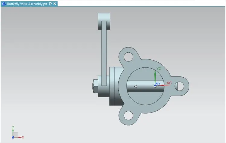
Front View
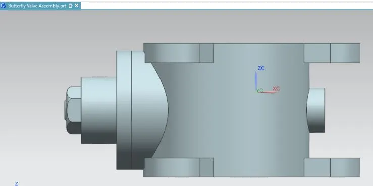
Left Side View
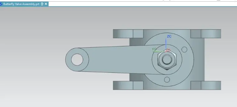
Right Side View
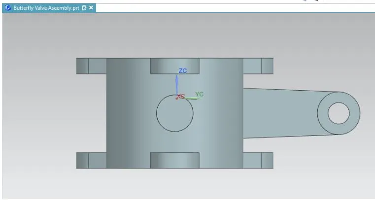
Isometric view
Applied GD&T to Butterfly Valve Assembly.
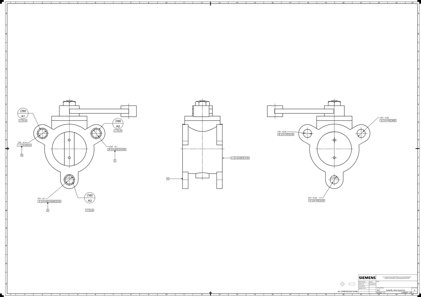
- For the assembly, GD&T is applied according to the fluid flow direction. The fluid flows through the large central hole of the butterfly valve.
- From the design, it is understood that the three ear like parts on both sides are the ones that comes in contact with the external pipeline. So one of the faces that containing the holes are taken as A datum.
- For A datum, we use datum target areas A1, A2 and A3 at the regions of the holes and each region is given a flatness tolerance of 0.25.
- Among the three holes, one is taken as B datum. It is given a perpendicularity tolerance of 0.25 at MMC with respect to A datum.
- The other hole is taken as C datum and it is given a position tolerance of 0.25 at MMC with respect to datums A and B.
- The 3rd hole is given a position tolerance of 0.5 at MMC with respect to datums A, B and C.
- There are 3 other similar holes exactly opposite to the 3 holes which was considered just now. So they should be perfectly aligned with the holes that were already given GD&T.
- In order to give the perfect alignment, the 3rd hole among the first 3 holes is taken as datum D in order to alingn the hole opposite to it with respect to D datum. The opposite hole is given a position tolerance of 0.75 at MMC with respect to datum D.
- Similarly holes opposite to B datum and C datum were also given position tolerance of 0.75 at MMC with respect to B datum and C datum respectively.
- The face containing the 3 opposite holes were given a profile of a surface tolerance with respect to A, B and C datums.
- The central large hole, through which the fluid flows is given a position tolerance of 0.5 at MMC with respect to A, B and C datums.
Thank you