Week 9 - Challenge 2 - Switch Bezel Design
SWITCH BEZEL
Tooling Axis Creation
As we have only three walls so we cant make the tooling axis directlty. we will another use the another method to create the tooling axis.
Creating tooling Axis for Y direction
First extract the base surface and create a point on the surafce at 0 and after that insert axis system at point which we created. Now select the positioned sketch select yz plane and in projection point select the point which we created. Reverse Horizontal and then click on ok. After that take intersection of Class A by clicking on intersect 3D elements. Now we will hide class A and we will get intersection. After getting we will create 2 lines on intersection 1 on left side and another 1 on right side. After that hide intersection sketch Now we can create a bisecting line in sketcher workbench click on bisecting line command and the select line 1 and line 2 after we will get a mean line. After make all the lines as construction element and then Exit from sketcher workbench. And we will get the tooling axis for Y direction.
Creating tooling Axis for X direction
Insert new positioned sketch on XZ plane on same projection point. After getting into the sketcher workbench intersect the Class A edges. Since we don't have another face to create a bisecting line so now we will create a line directly in Z direction which will will be 3 to 4 degree from the Axis because we know that minimum degree of Class A is 3deg. After that Exit the sketcher workbench so we will get the tooling axis for X direction.
Creating Final Tooloing Axis
Now we will bisect these two line to get Final tooling Axis. we can bisect these line using the line command in the 3D itself. In line command select line type Bisecting and after that select line 1 and line 2 an select point and ok. After hiding everything we will get Final Tooling Axis. And we can use this tooling axis for draft analysis.
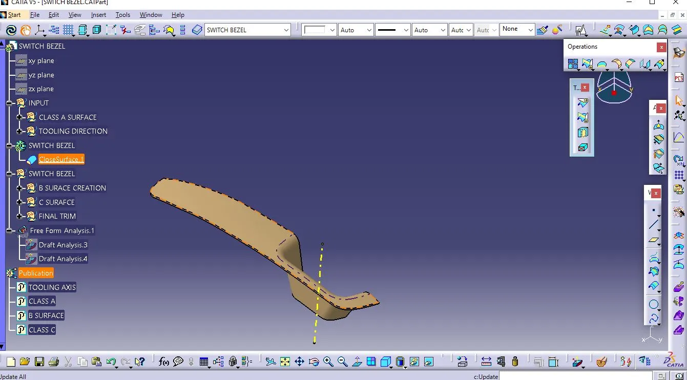
ISOMETRIC VIEW
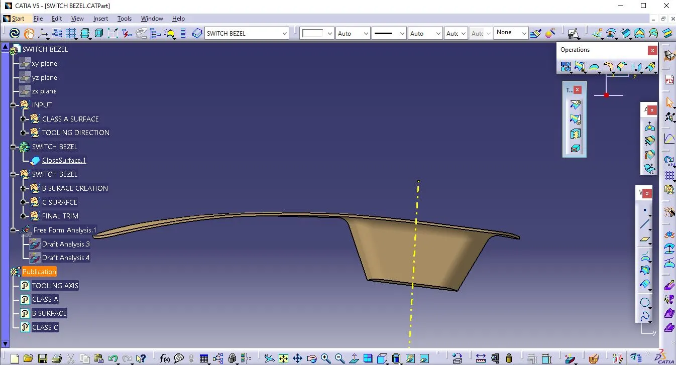
FRONT VIEW
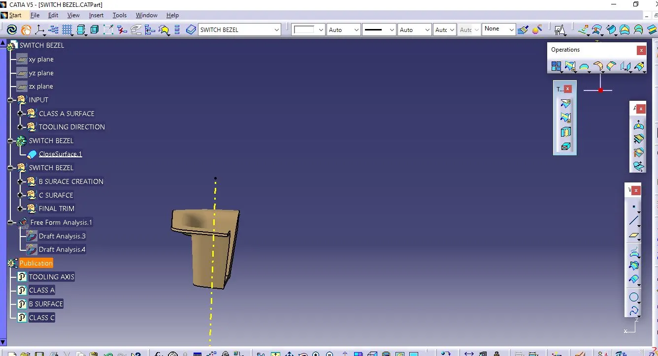
TOP VIEW
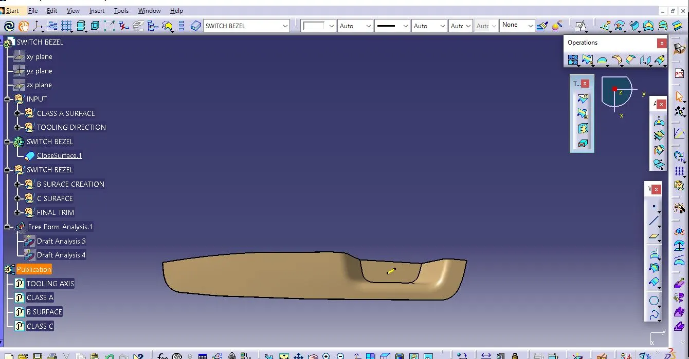
RIGHT VIEW
DRAFT ANALYSIS ON CLASS A
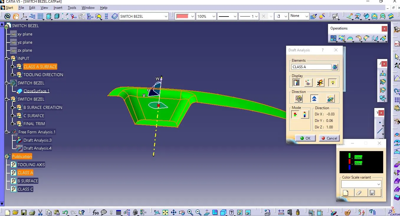
After creation of tooling axis apply material mode on Class A to perform Draft analysis. Click on Draft analysis features click on compaas which is used to define the draft direction and move it towards tooling axix and align with it after alinging the compaas lock it after that select the element to draft analys. Here we will do draft analysis for 3 degree the green colour will for above 3degree and the red is for 0 to 3 degree and blue is for negative. In display there is a running point option through which we can check the degree of the element at any point by running it over the surface.
As got the degree for Bezel Rest Surface 88 degdirect, Base 85.51 degdirect, side wall 20.37 degdirect and backwall 3.38 degdirect.
DRAFT ANALYSIS ON FINAL COMPONENT
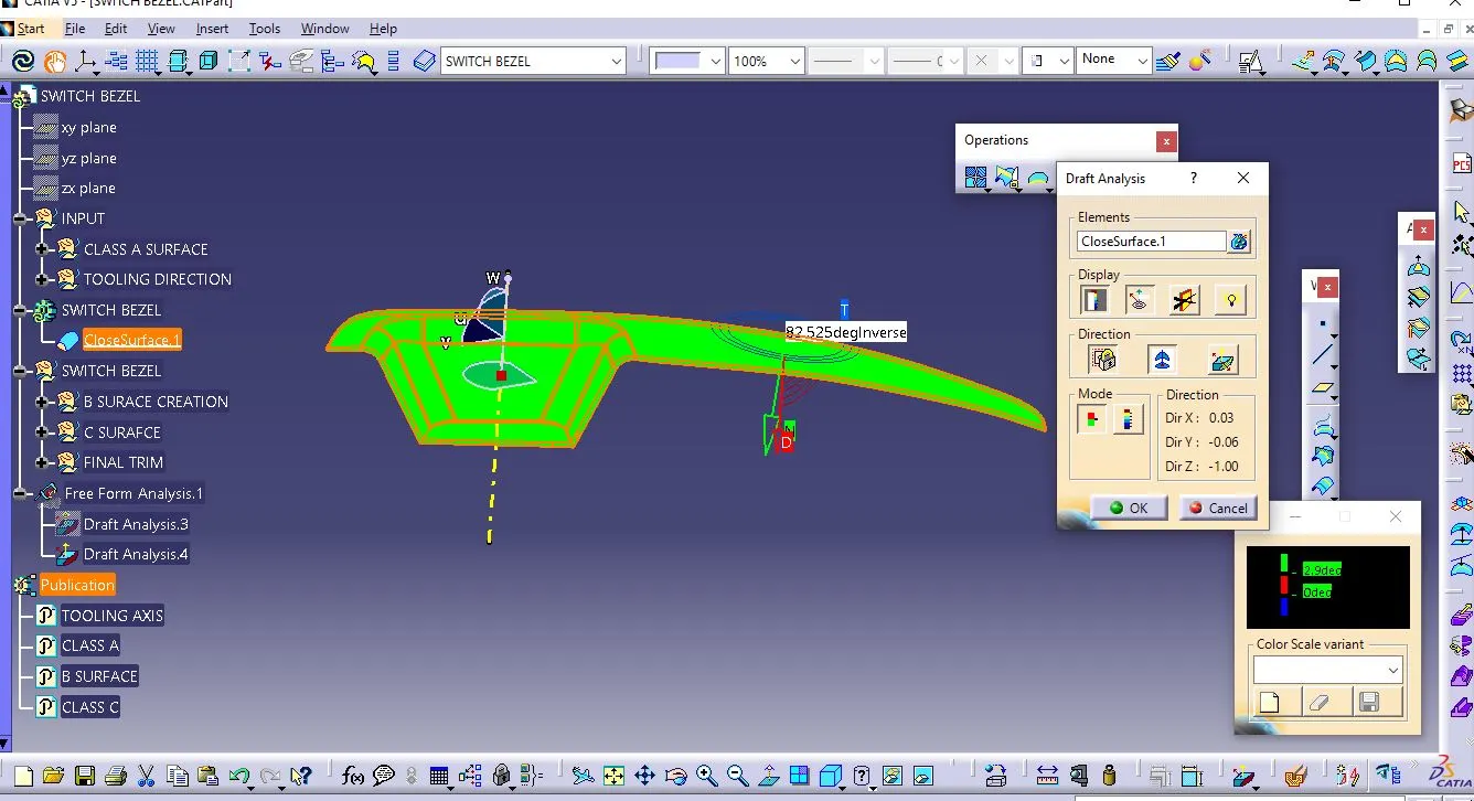
After creation of final component which is closed surface body follow the same steps for draft Analysis on final component.
As i got the degree for Bezel Rest Surface 88 deginverse, Base 85.51 deginverse, side wall 20.37 deginverse, backwall 3.38 deginverse and thickness of body is 3 deginverse.