Week 9 - Challenge 3 - Bumper
BUMPER
Tooling Axis Creation
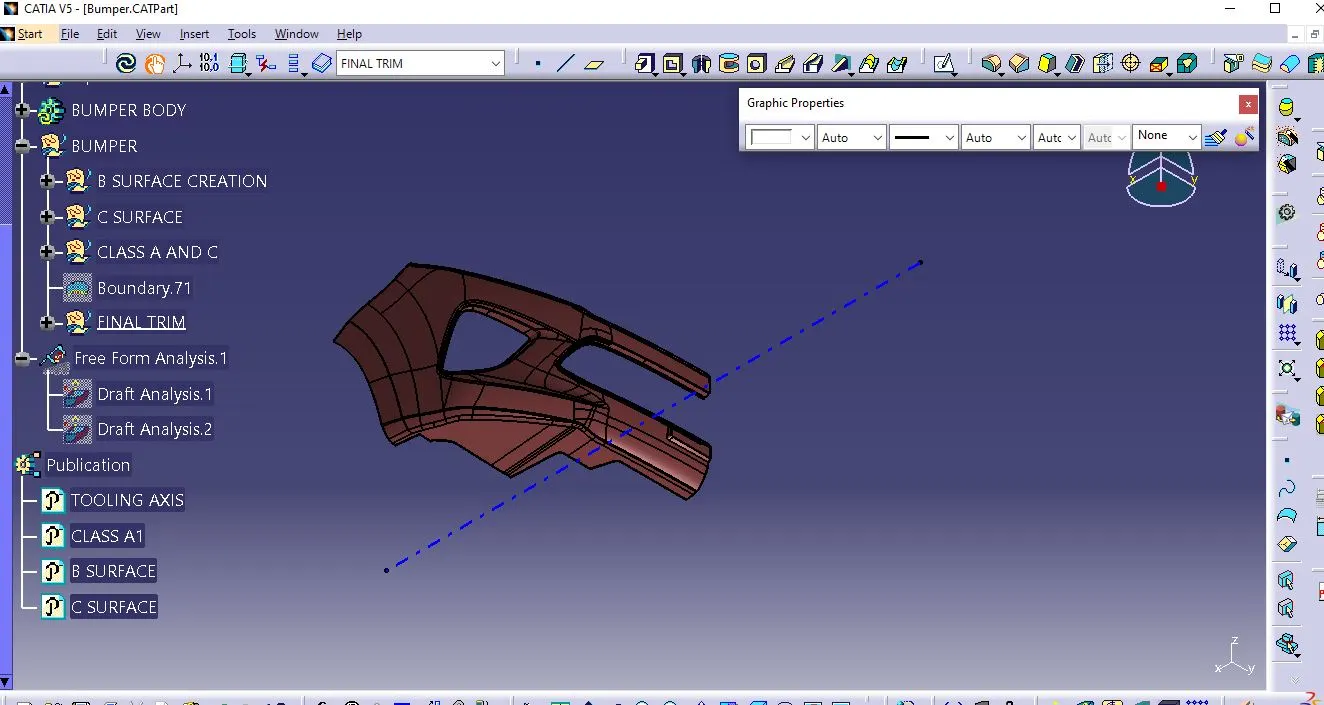
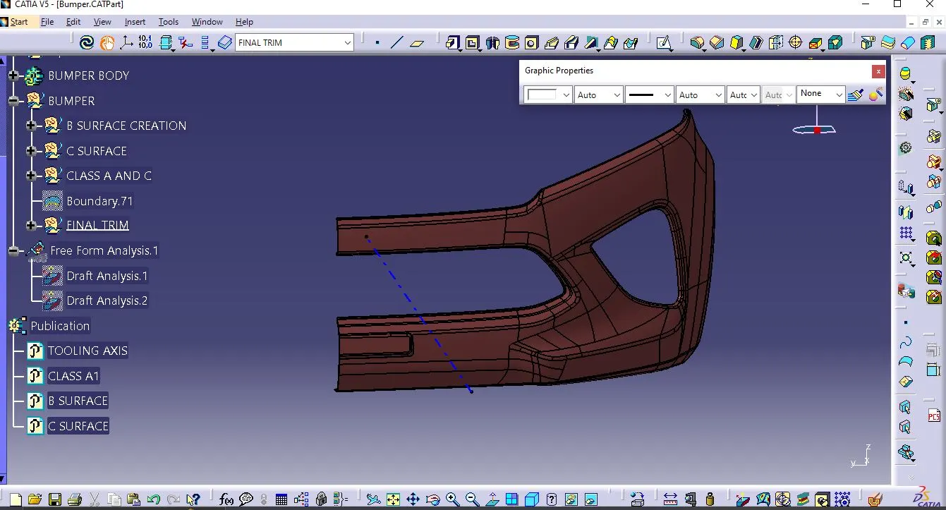
Create a point on curve in X direction after that create line in point direction and extend it as required. After creating the do test draft analysis of Class A to whether the line can be used as Tooling Axis if the draft analysis is ok then use this line as a Tooling Axis.
Isometric View
Back View
Left View
Bumper Closed Body
Draft Analysis of Class A
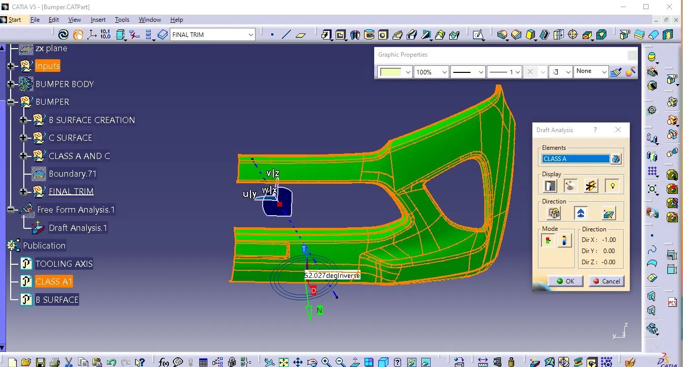
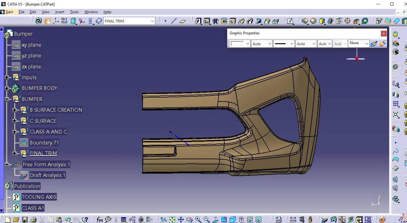
After creation of tooling axis apply material mode on class A to perform Draft Analysis. Click on draft analysis feature click on compass which is used to define the draft direction and move it towards the tooling axis and align with it. After alinging the compass lock it after that select the element to draft analys. Here we will do draft analysis for 3deg the green colour will for above 3deg and red is for 0 to 3deg and blue is for negative. In display there is a running point option through which we can check the deg of the element at any point by running it over the surface.
As we got the degree for Bumper surface is 85.957 deginverse for front top, 26.879 deginverse from side.
Draft Analysis of Final Component
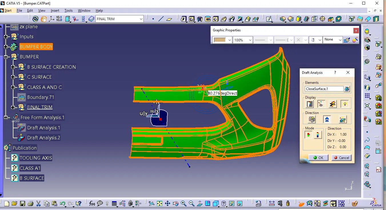
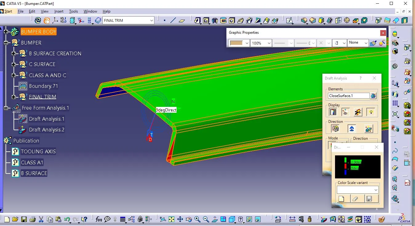
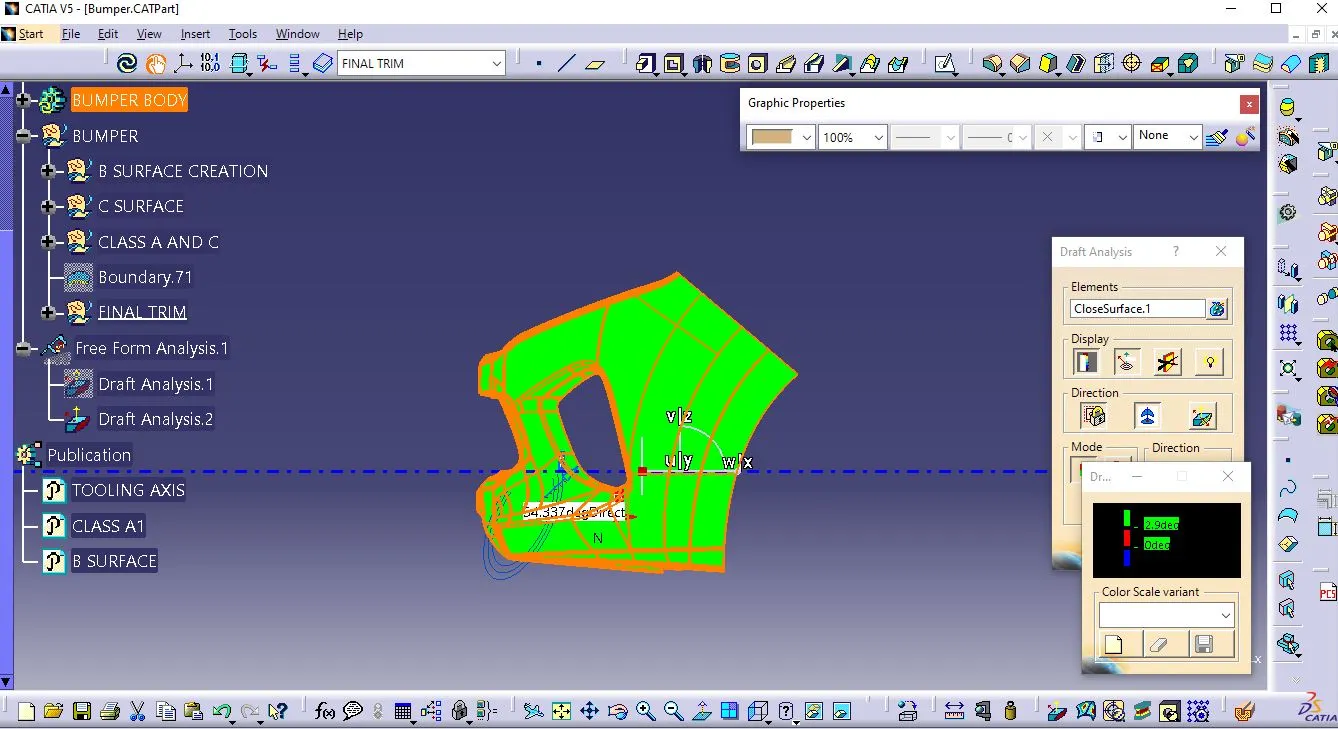
After creating final component which is closed surface body follow the same steps for draft analysis for final component.
Here in Bumper some Faces are perpendicular to Axis and some are parallel to axis. For perpendicular i used sweep with reference to draft for 3degree. And for Parallel i used sweep with refernce to surface for 90degree.
As is got the degree for Bumper 85.436 degdirect front top and the thickness is 3degdirect.