Week 14 challenge
OBJECTIVE
- The goal is to use Siemens NX CAD's modelling and assembly features to design and assemble the butterfly valve's components.
- Utilizing a variety of drafting instruments to create the butterfly valve assembly drawing sheets.
- Recognizing and using the several GD&T symbols for the butterfly valve assembly.
INTRODUCTION
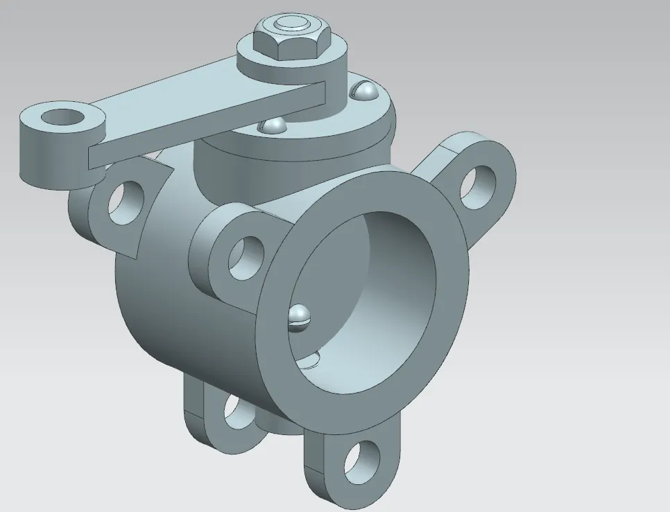
One kind of flow control device that is frequently utilized in pipelines and other industrial application is the butterfly valve. It is typified by a straightforward but efficient design, with a circular disc or "butterfly" rotating on a central axis to control fluid flow. The disc aligns parallel to the flow when the valve is fully open, allowing the pipeline to flow at its maximum capacity. On the other hand, the disc blocks the flow when it is closed because it rotates perpendicular to the flow. This adaptable valve is highly valued for its small size, simplicity of use, and fast shut-off times, which make it perfect for situations requiring quick flow adjustments and limited space.
COMPONENTS OF BUTTERFLY VALVE
Body
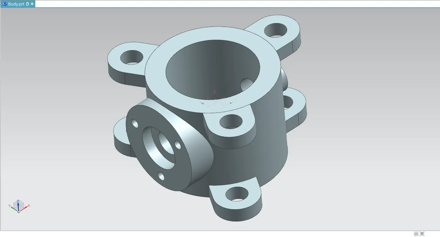
The body is the main structural component of the butterfly valve. It houses the internal components and provides the connection to the pipeline. The function of the body, the body connects to the pipeline flanges and contains the internal seating for the disc and seat.
Stem
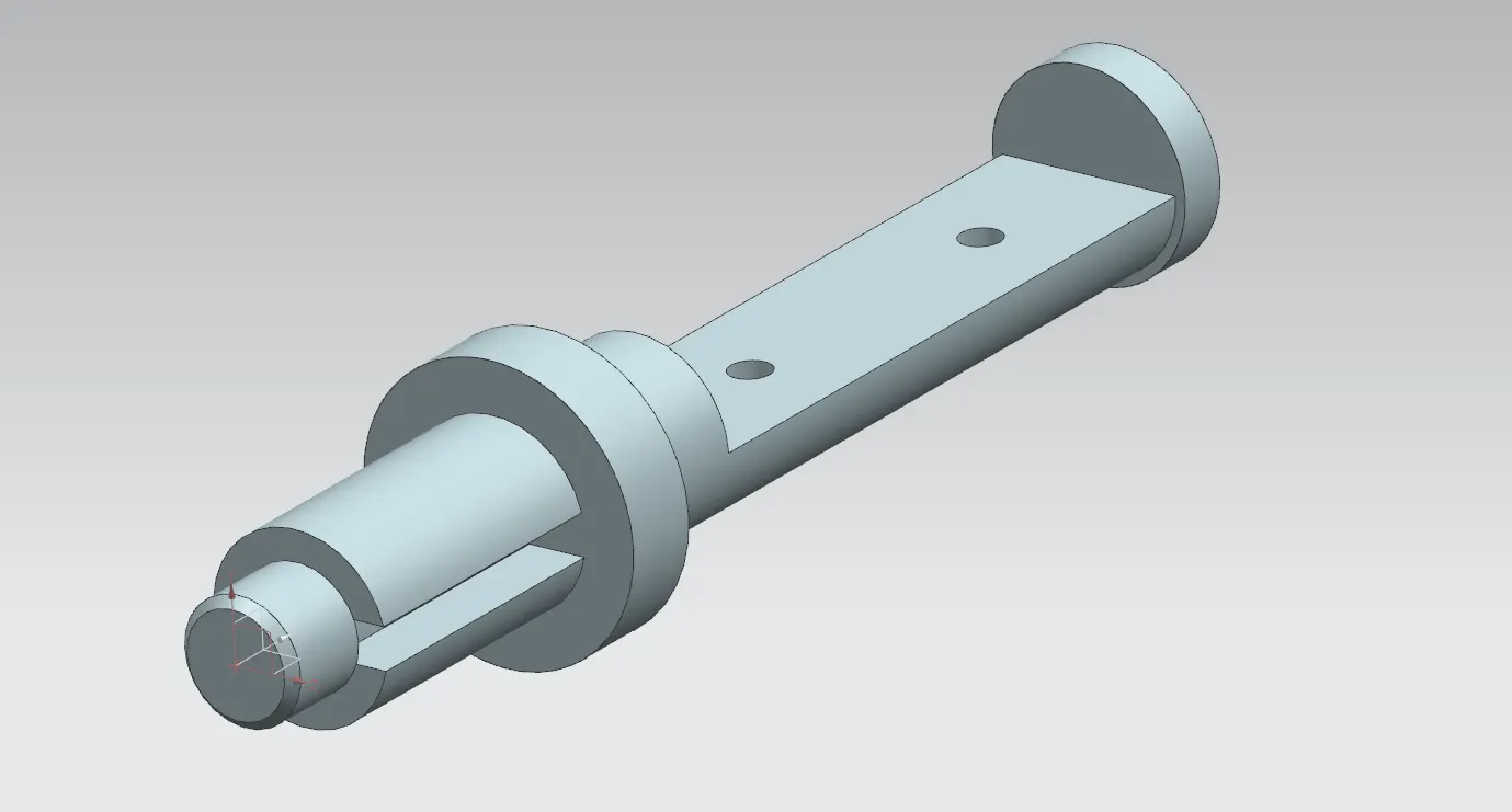
The stem is the central rod that extends through the valve body and connects the disc to the actuator or lever mechanism. Transmits the rotational force from the actuator or lever to the disc, enabling it to pivot and control the flow of fluid. It is also called as Shaft.
Top Flange
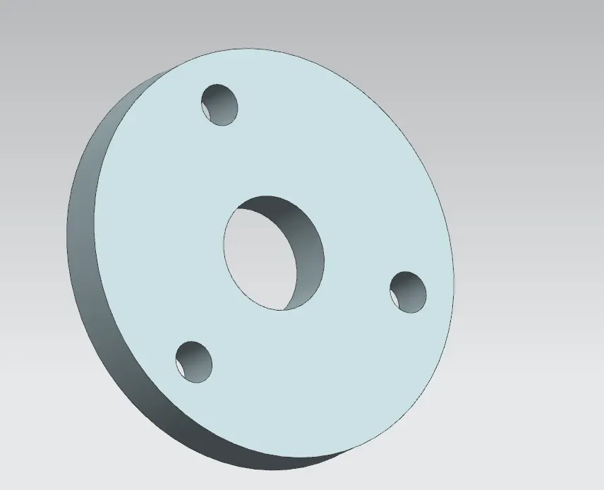
The top flange is a flat, circular component that is part of the valve body and connects the valve to the actuator or manual handle. Provides a mounting point for the actuator or lever mechanism. It ensures proper alignment and attachment of the actuator or manual control. It is also known as Retainer.
Disc
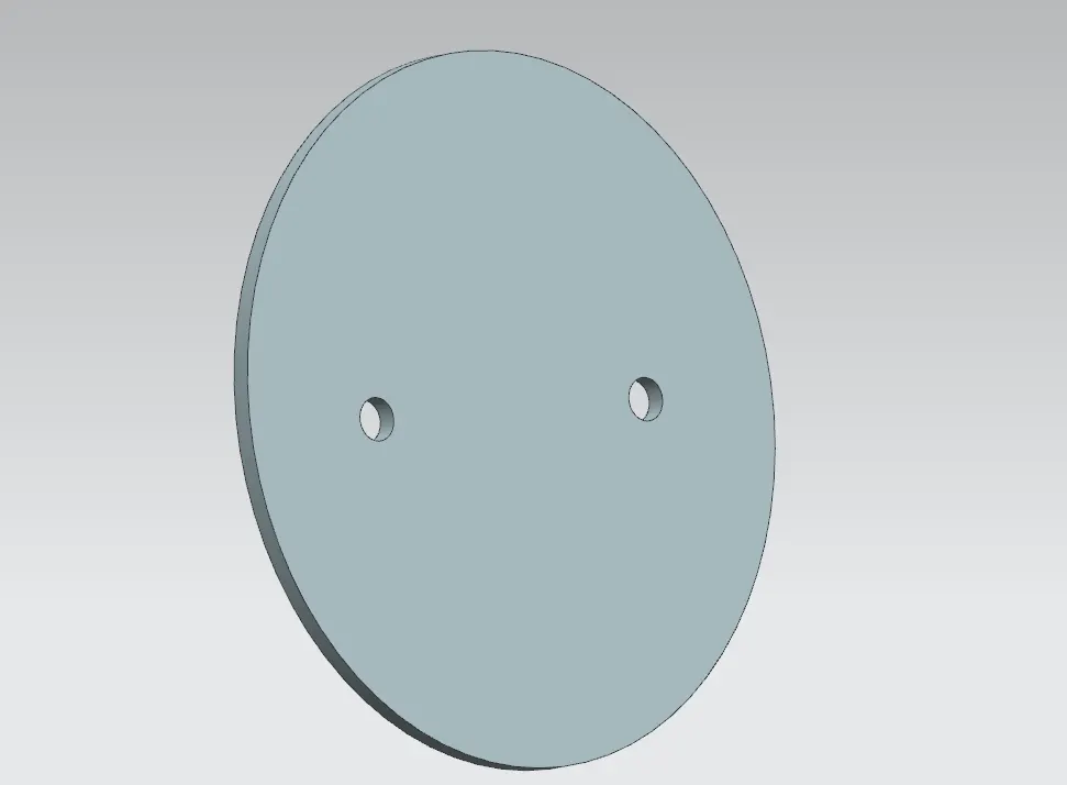
The disc, also known as the "butterfly", is a circular plate that pivots around a central axis within the valve body. The disc controls the flow of fluid through the valve by rotating to either open or close the flow path. When parallel to the flow, it allows fluid to pass. when perpendicular, it blocks the flow.
Lever
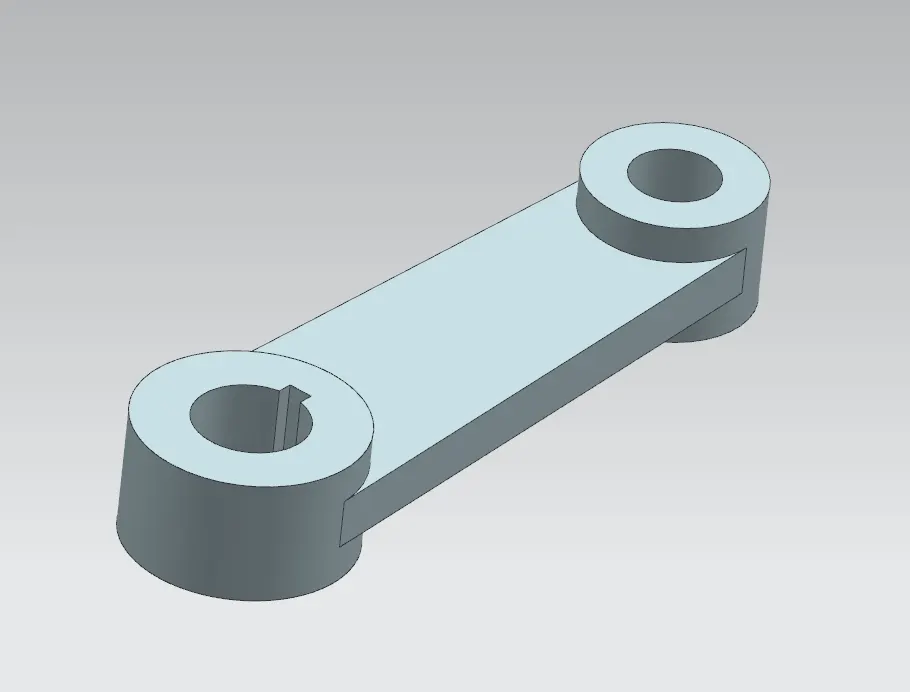
The lever is a manual control mechanism used to operate the valve. It is often a simple handle attached to the top flange or stem. When manually operated, the lever rotates the disc to open or close the valve. It is used in conjunction with the top flange and stem to control the valve's position.
Nut
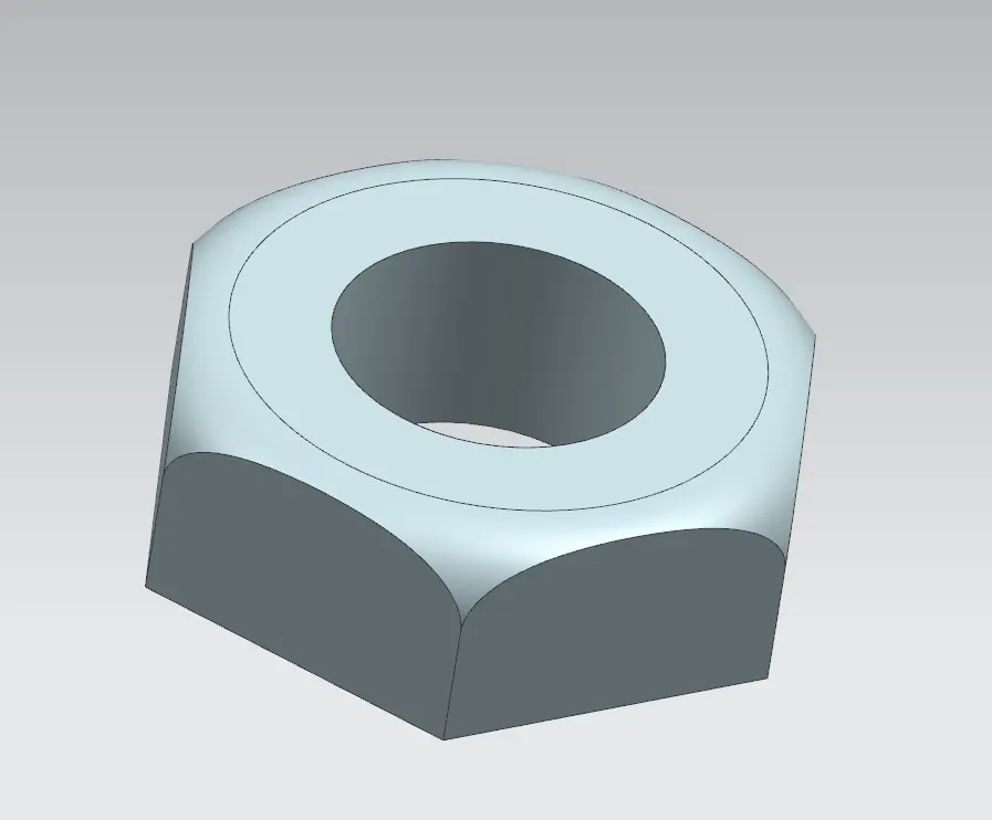
The nut is a fastening component used to secure the lever or actuator to the valve body. It is often found on the top flange or stem assembly. Ensures that the lever or actuator is firmly attached and properly aligned with the valve's operational components.
DESIGN OF THE COMPONENTS
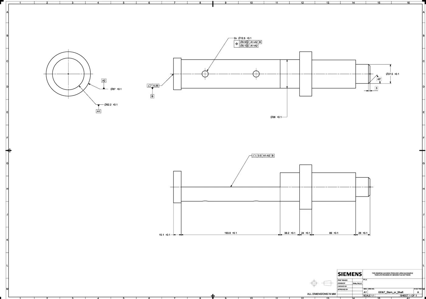
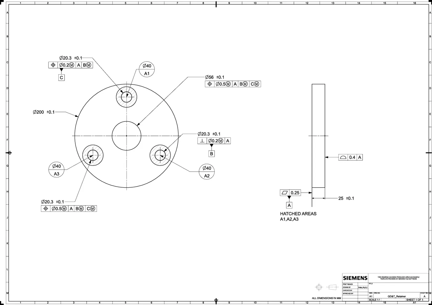
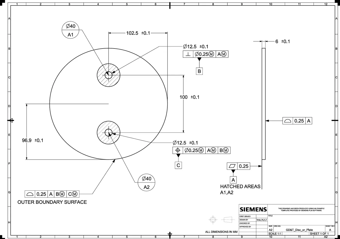
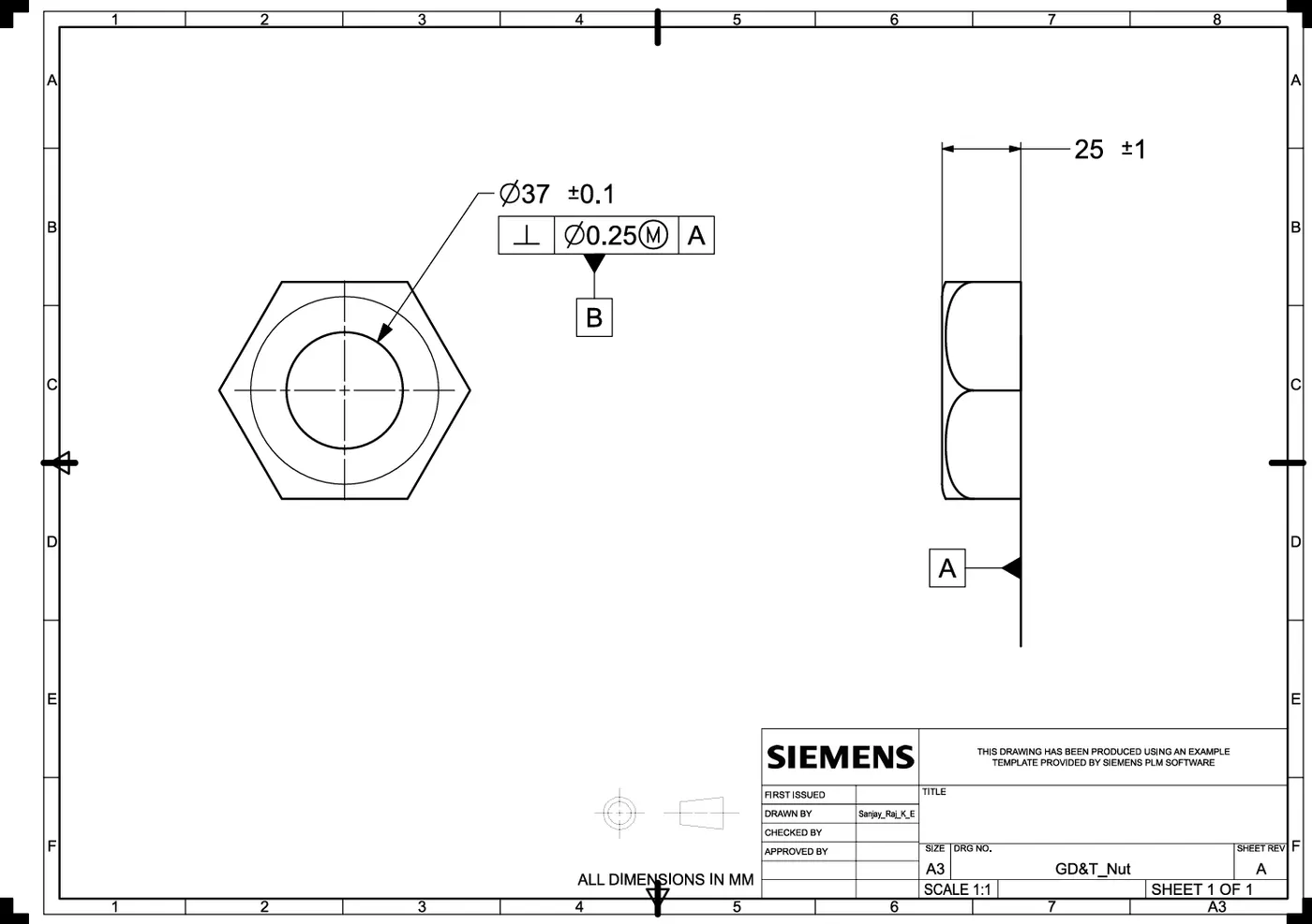
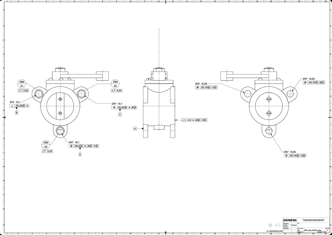
This section contains the processes or procedure that I followed to create each part, along with images. It also includes images of the drawing with the GD&T symbols.
Body
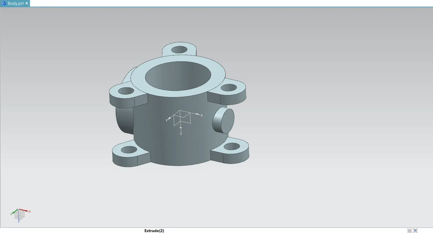
- The body of butterfly valves typically slide between two pipe flanges. With its protruding lug body design, this butterfly valve offers bolt holes that lines up with the pipe flange's holes.
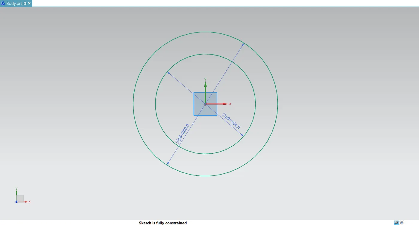
- To create a cylindrical body or housing, make two circles with the necessary diameter and then use the extrude command.
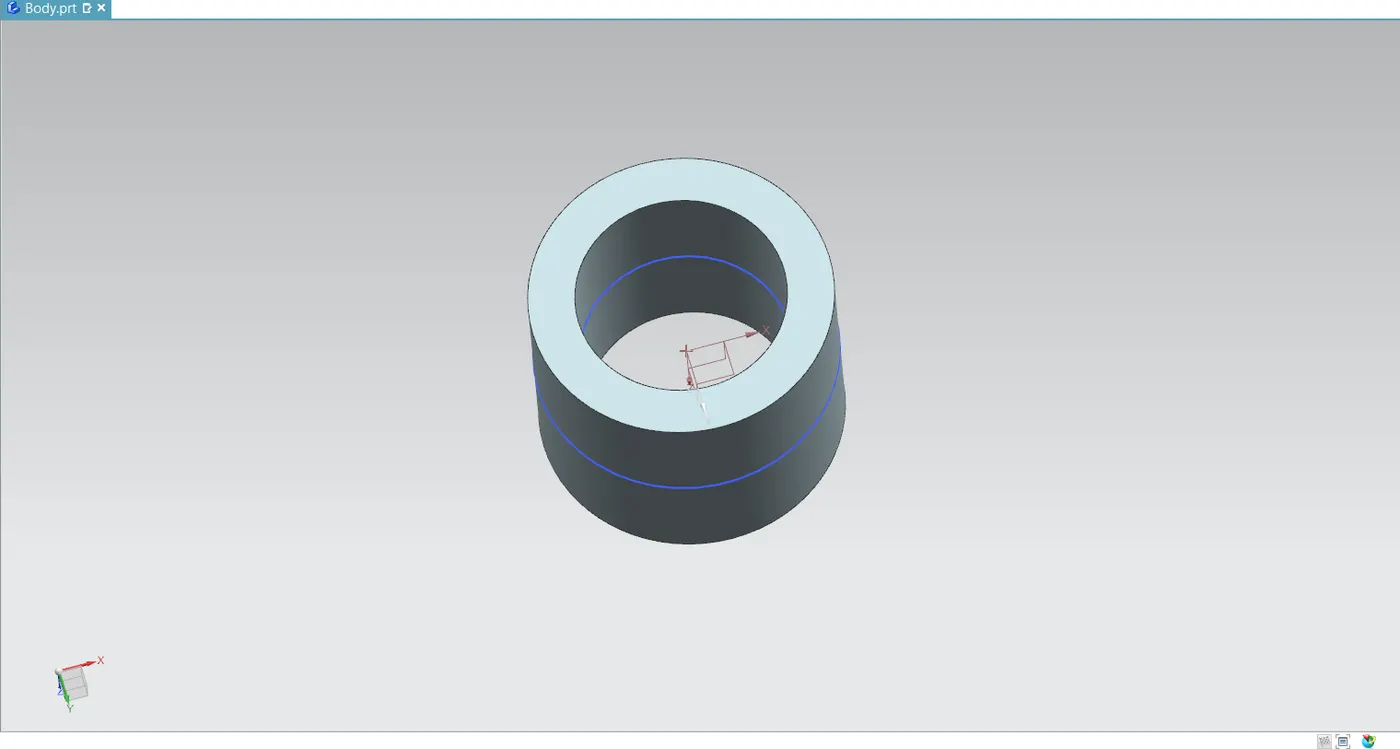
- Create three lugs with holes on that cylindrical body. This will make it easier for us to attach the pipe flange to the butterfly valve. In order to achieve a symmetrical valve, we first generated the lugs on the mid-plane and then extruded them with reference to it.
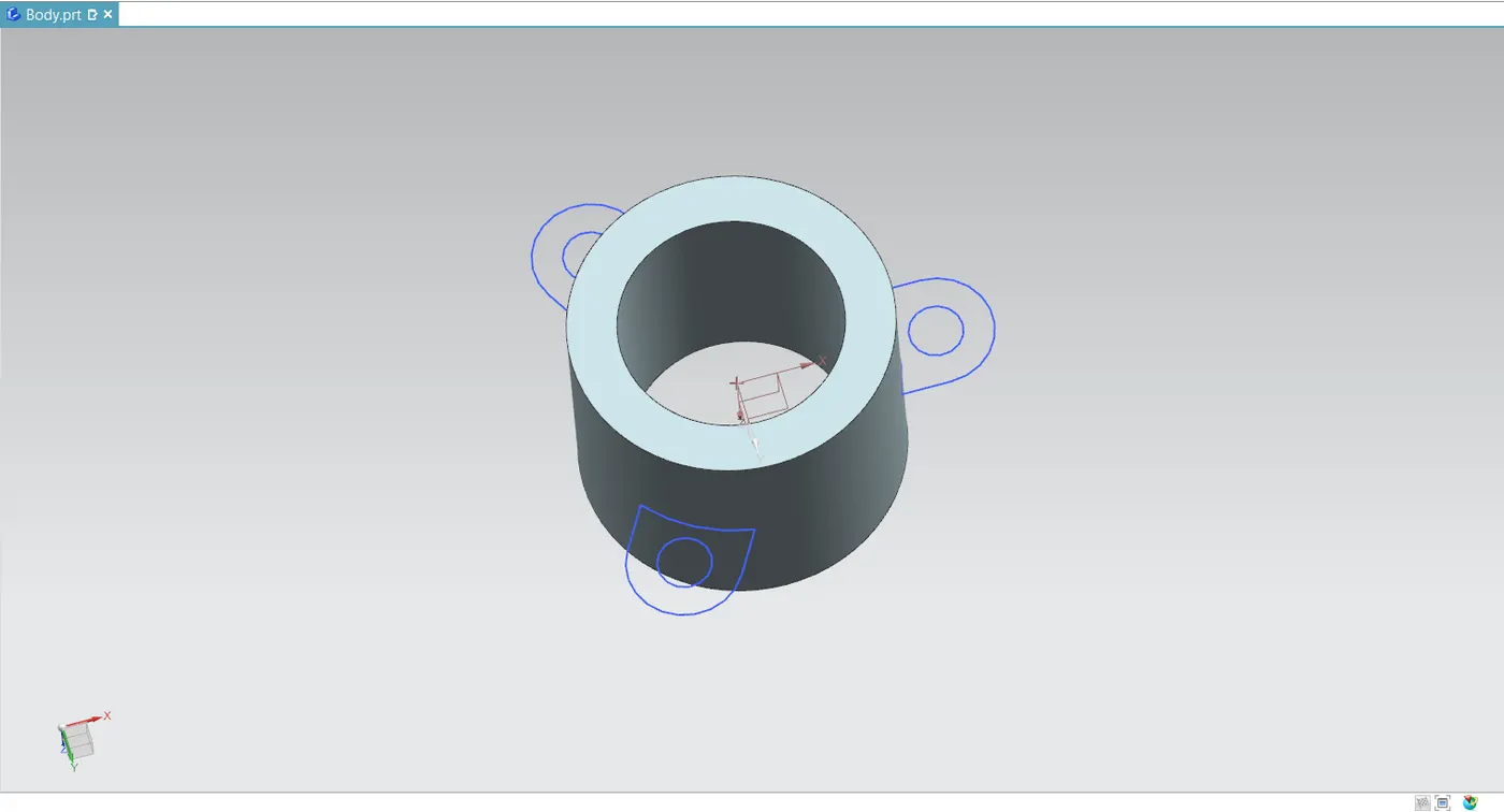
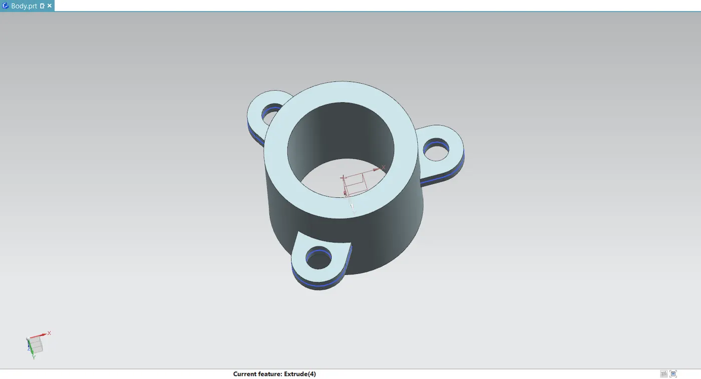
- With the aid of previously made lugs, we produced comparable lugs on the exterior surfaces of the body using the move object command.
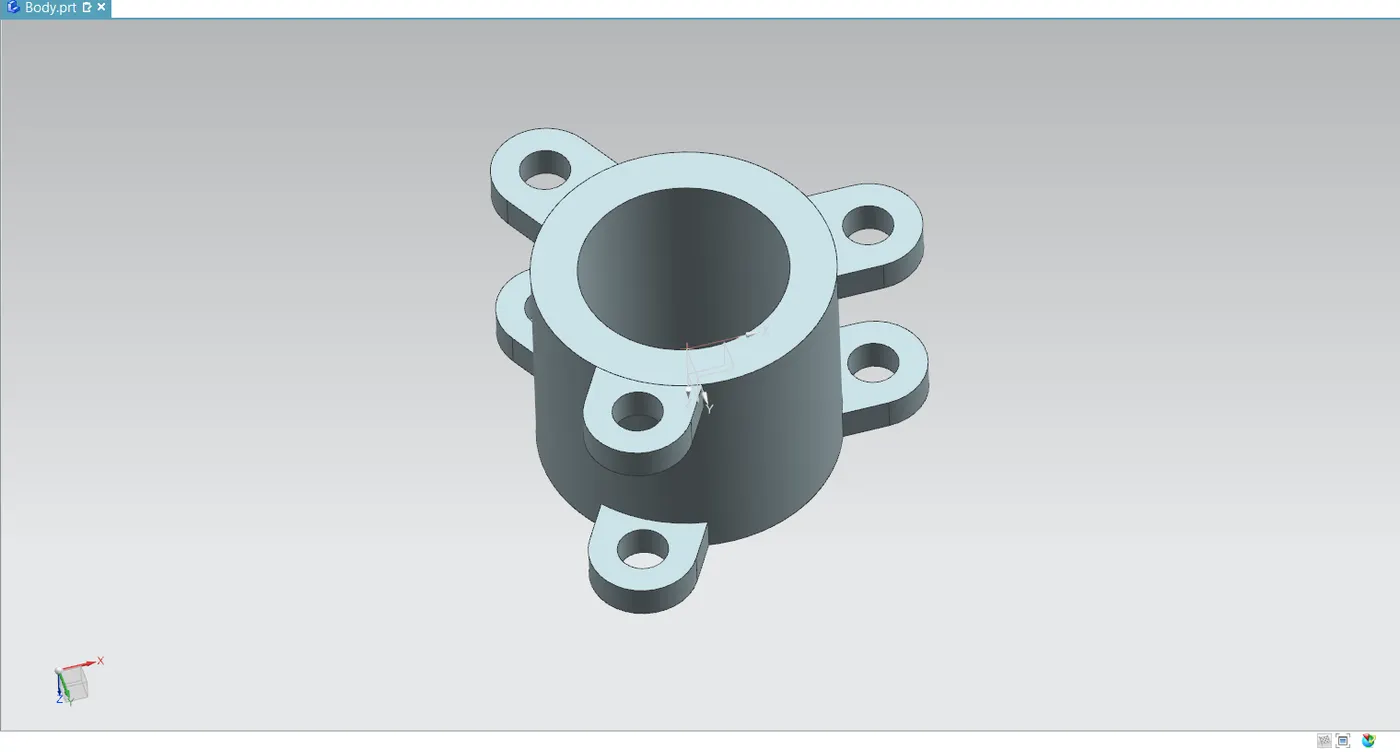
- Make a new datum plane and draw a circle with the necessary diameter. Use the extrude command to extrude this sketch up to the cylindrical body.
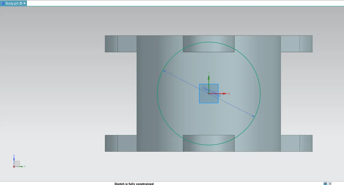
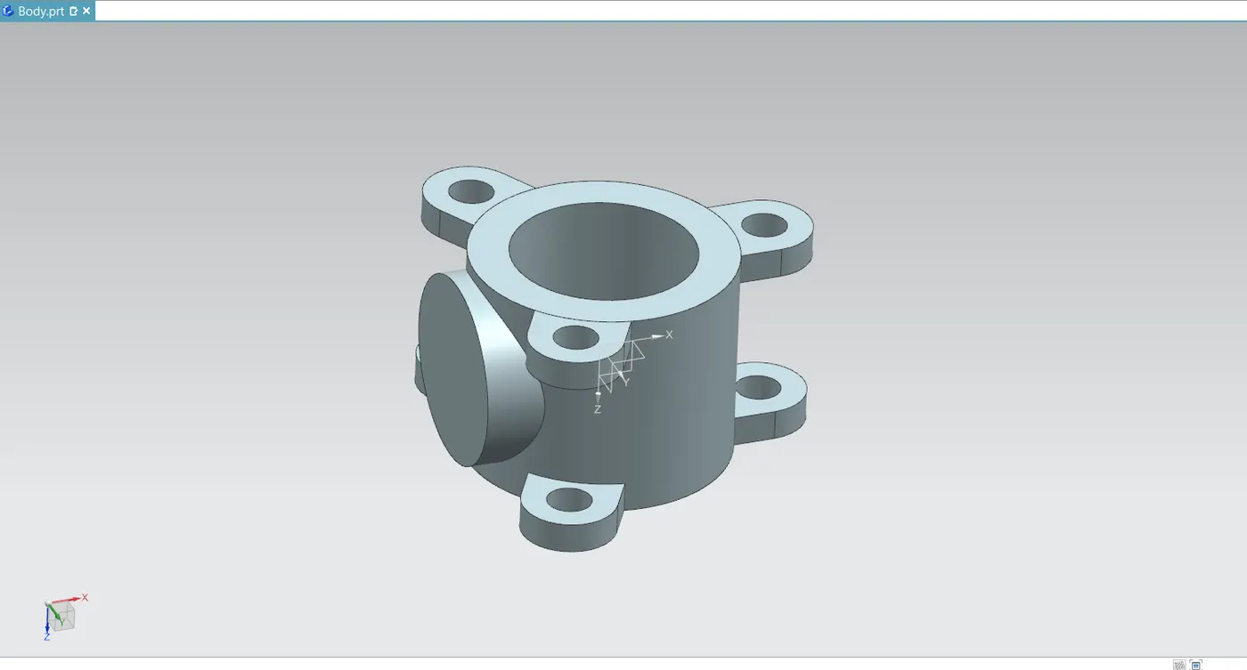
- Next, use the hole command to make counterbored holes in the body so that a shaft or stem may be inserted. Enter the necessary diameter and the hole depth parameters in the appropriate ranges.
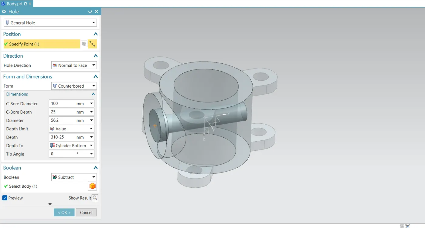
- On the opposite side of this recently formed feature, establish another datum plane. On this new plane, draw a circle, then extrude it up to the cylindrical body.
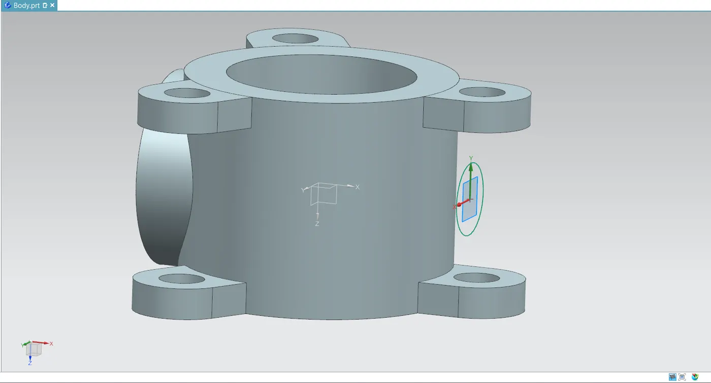
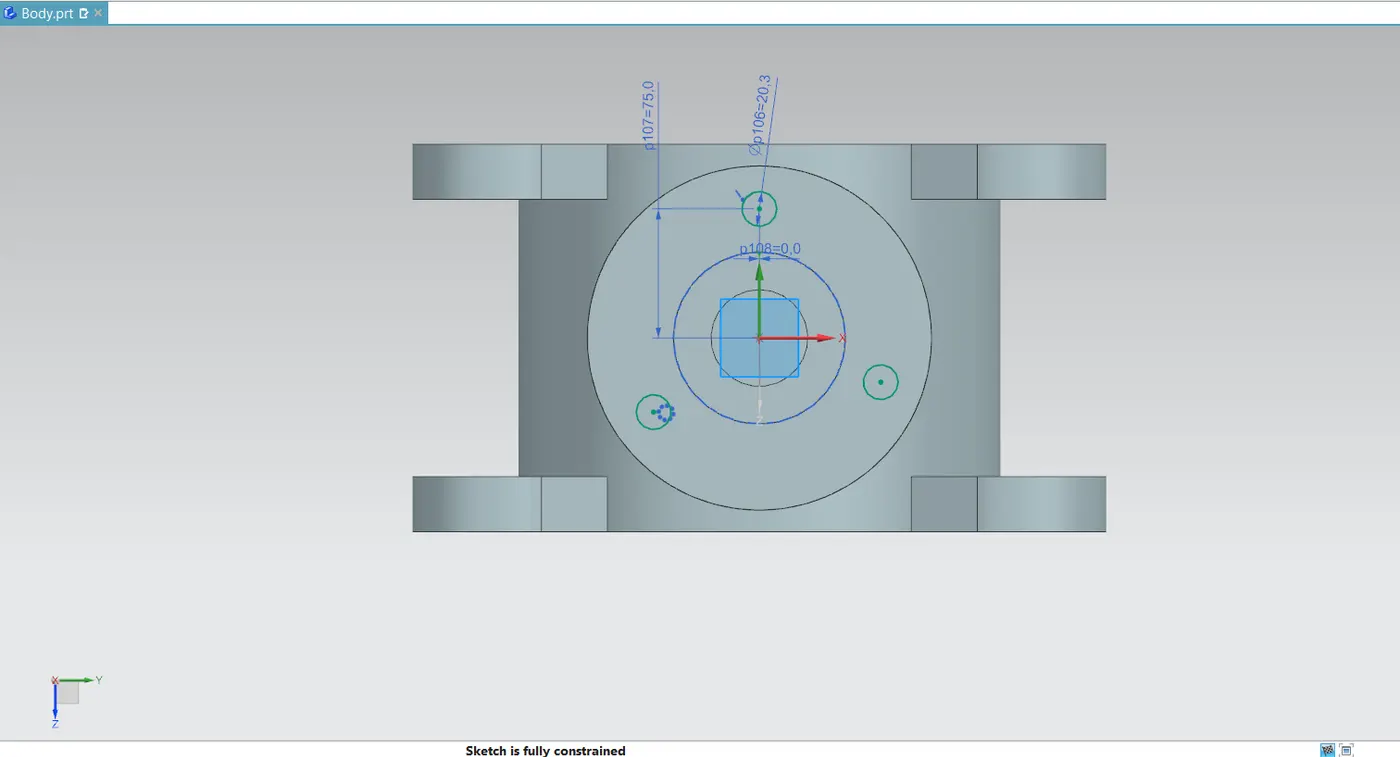
- To enable the assembly of additional body components, use the extrude command to drill three tiny holes on the exterior of the parent feature of the counterbored hole.
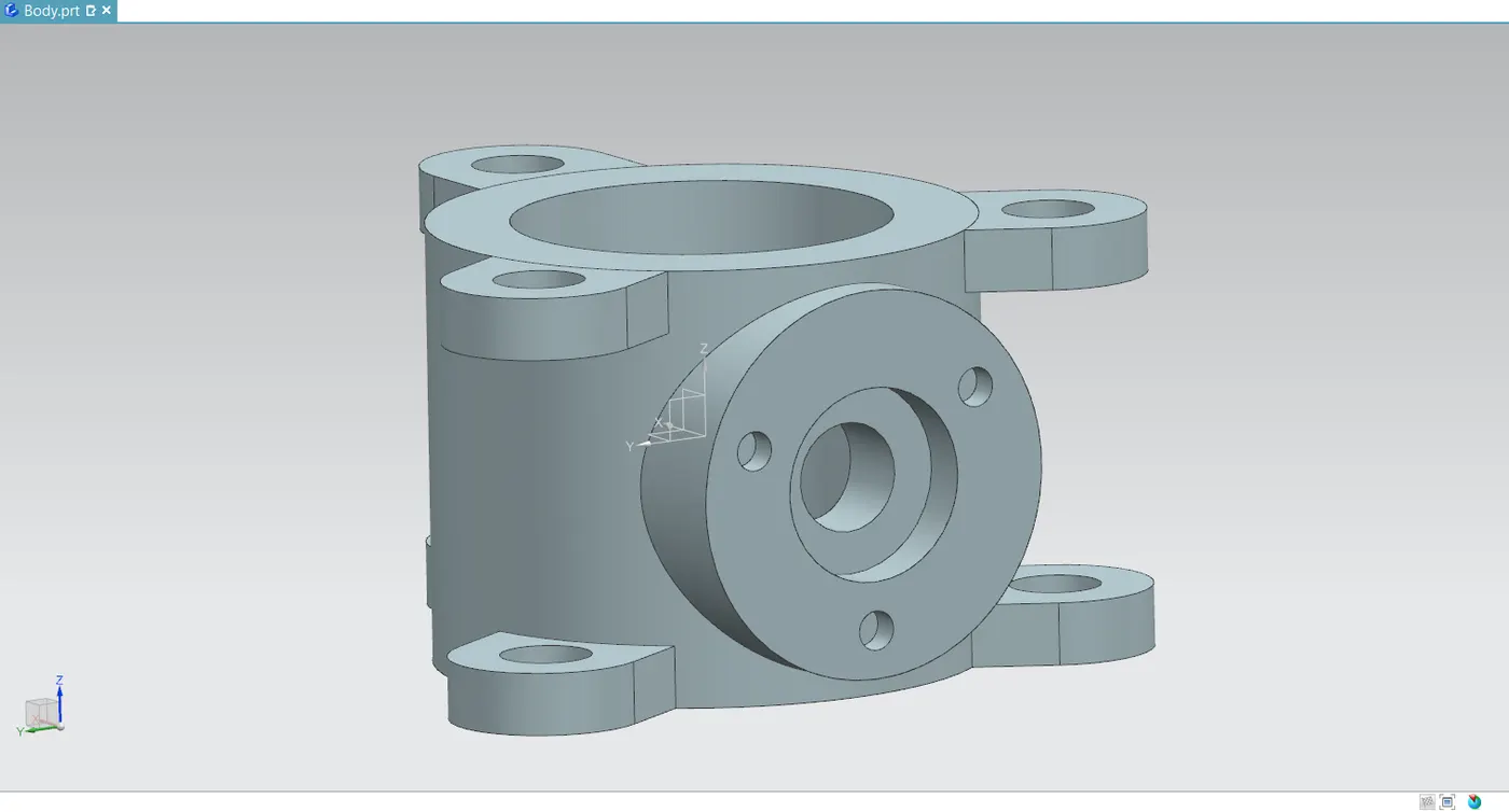
- Use the unite command to combine all the features into single object.
Stem
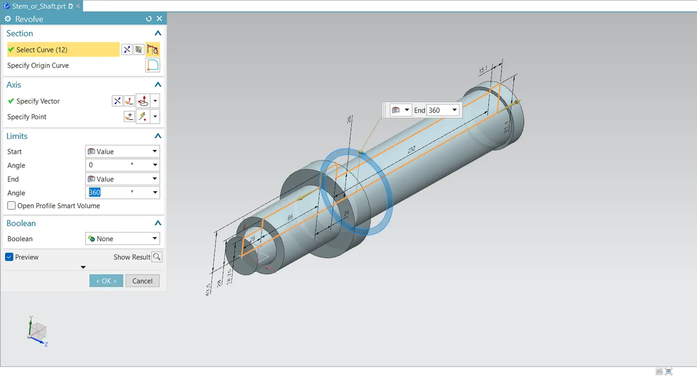
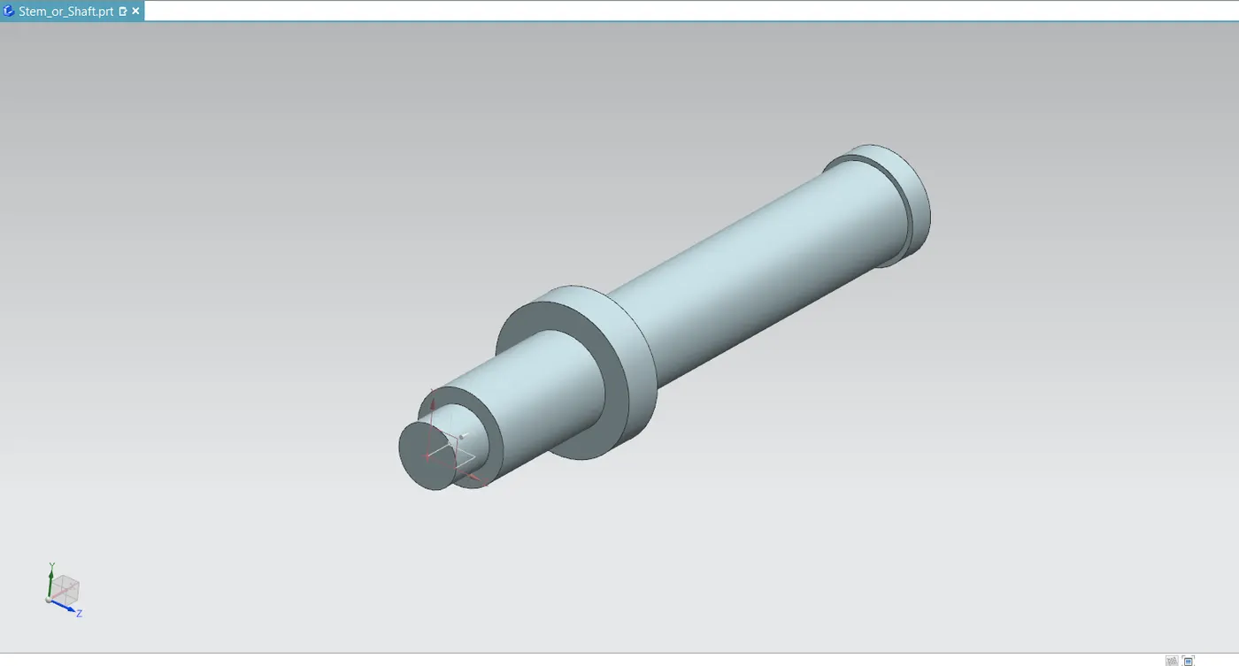
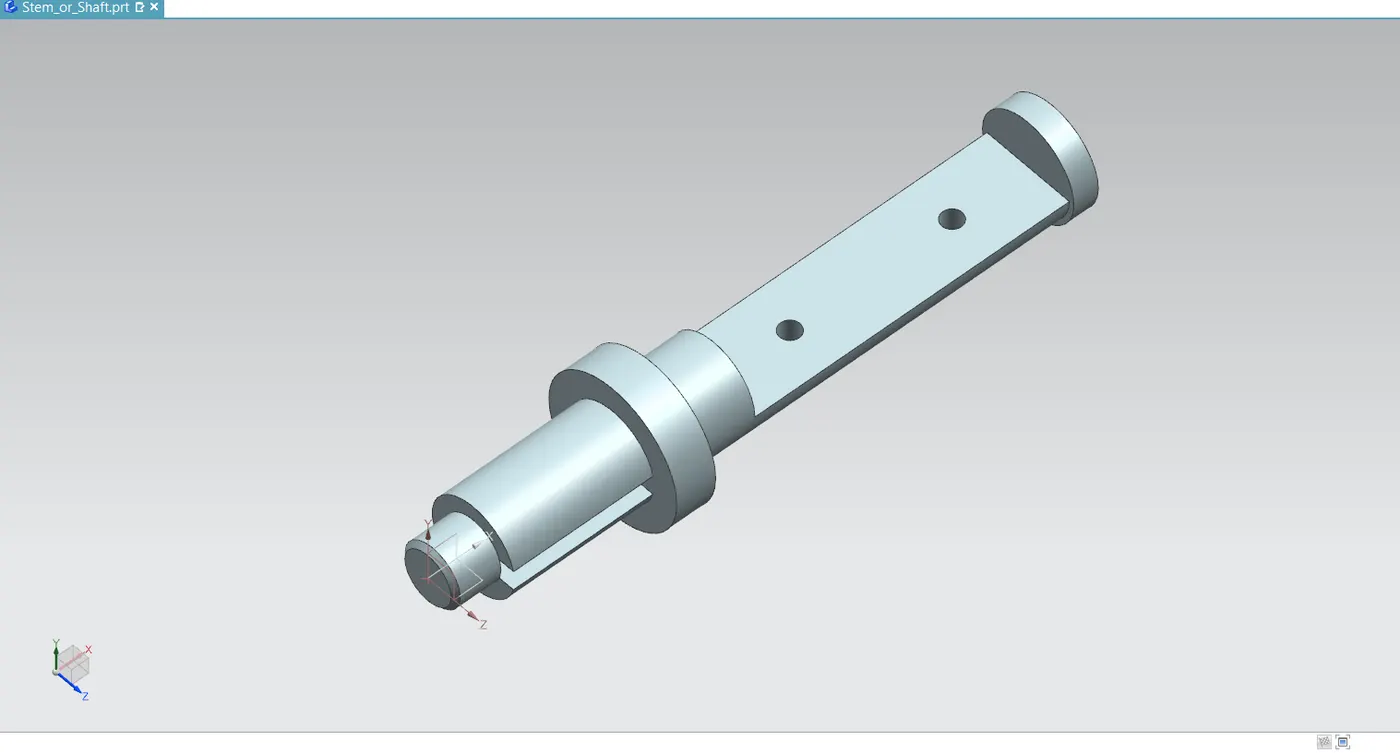
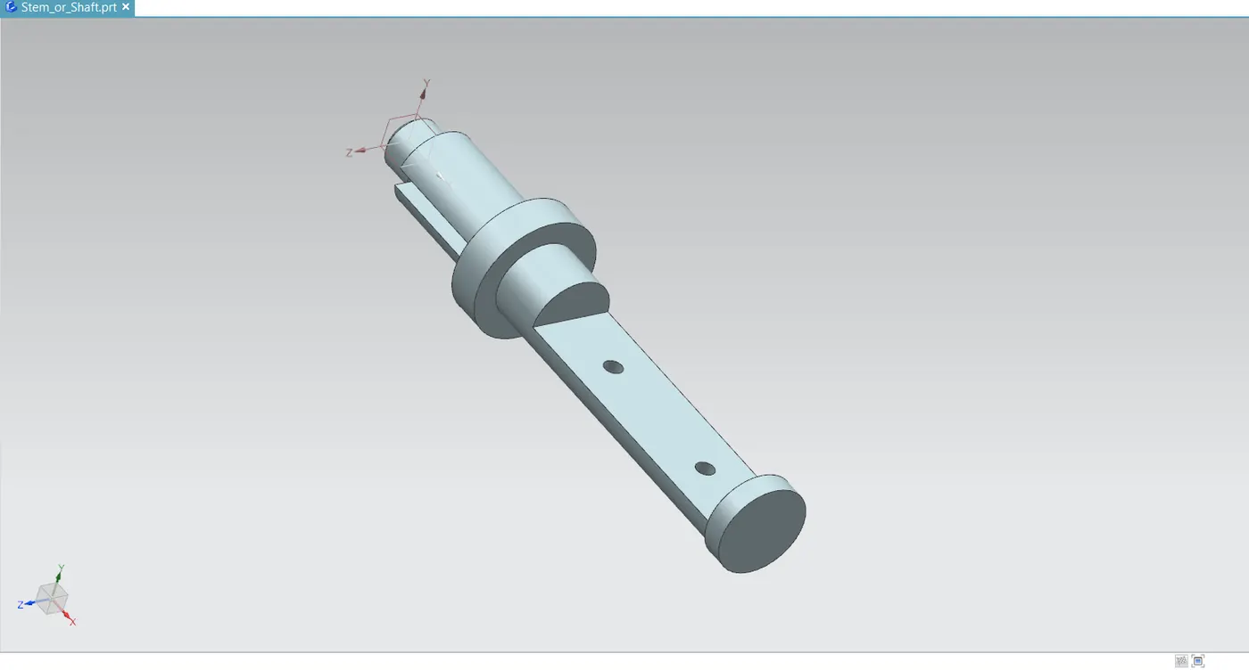
- The butterfly valve's stem might have a split-stem design or be a single-piece shaft. The shaft in this design is made of a single piece. This shaft is where the lever, nut, and disc/plate are attached.
- Initially, draw a cylindrical sketch with steps included. The revolve command cannot be used until that drawing is completely closed and confined.
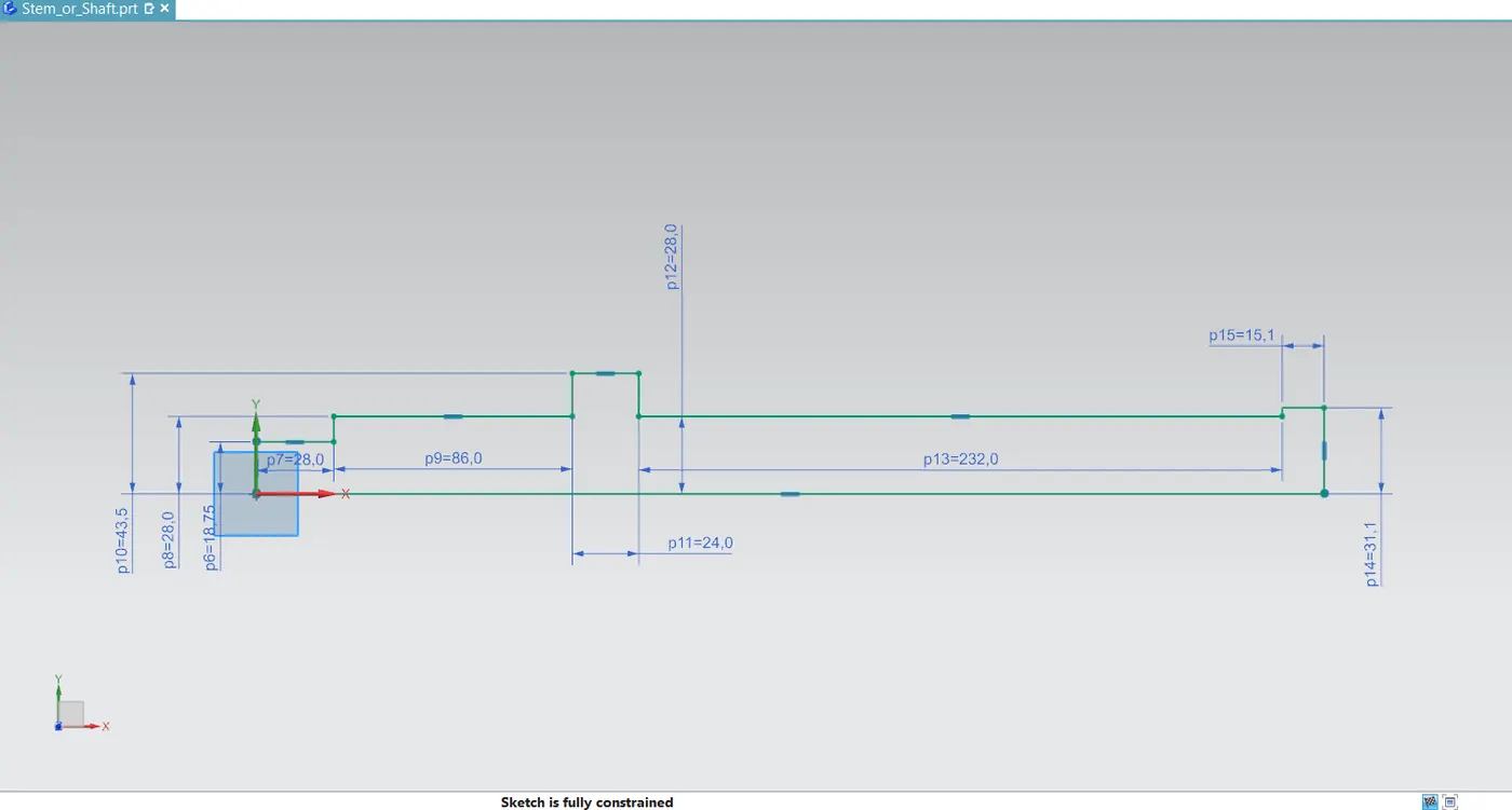
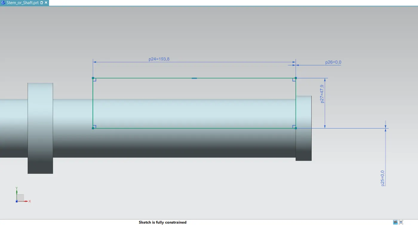
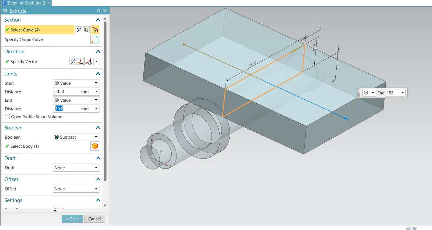
- Two rectangular slots must be made on the main body after it has been created.
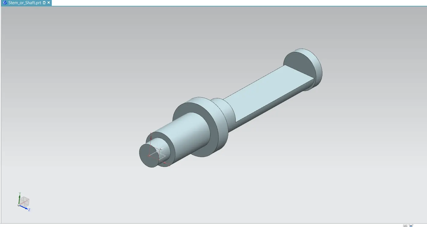
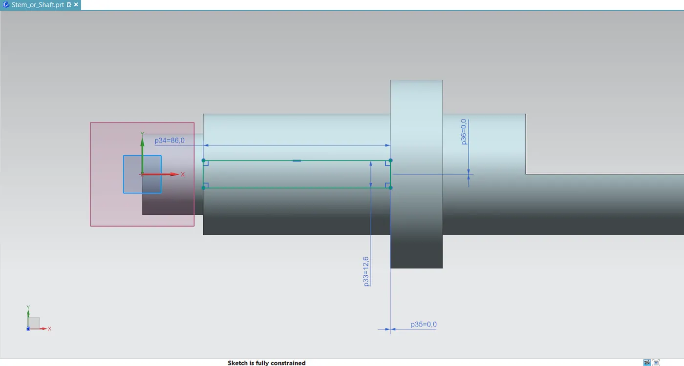
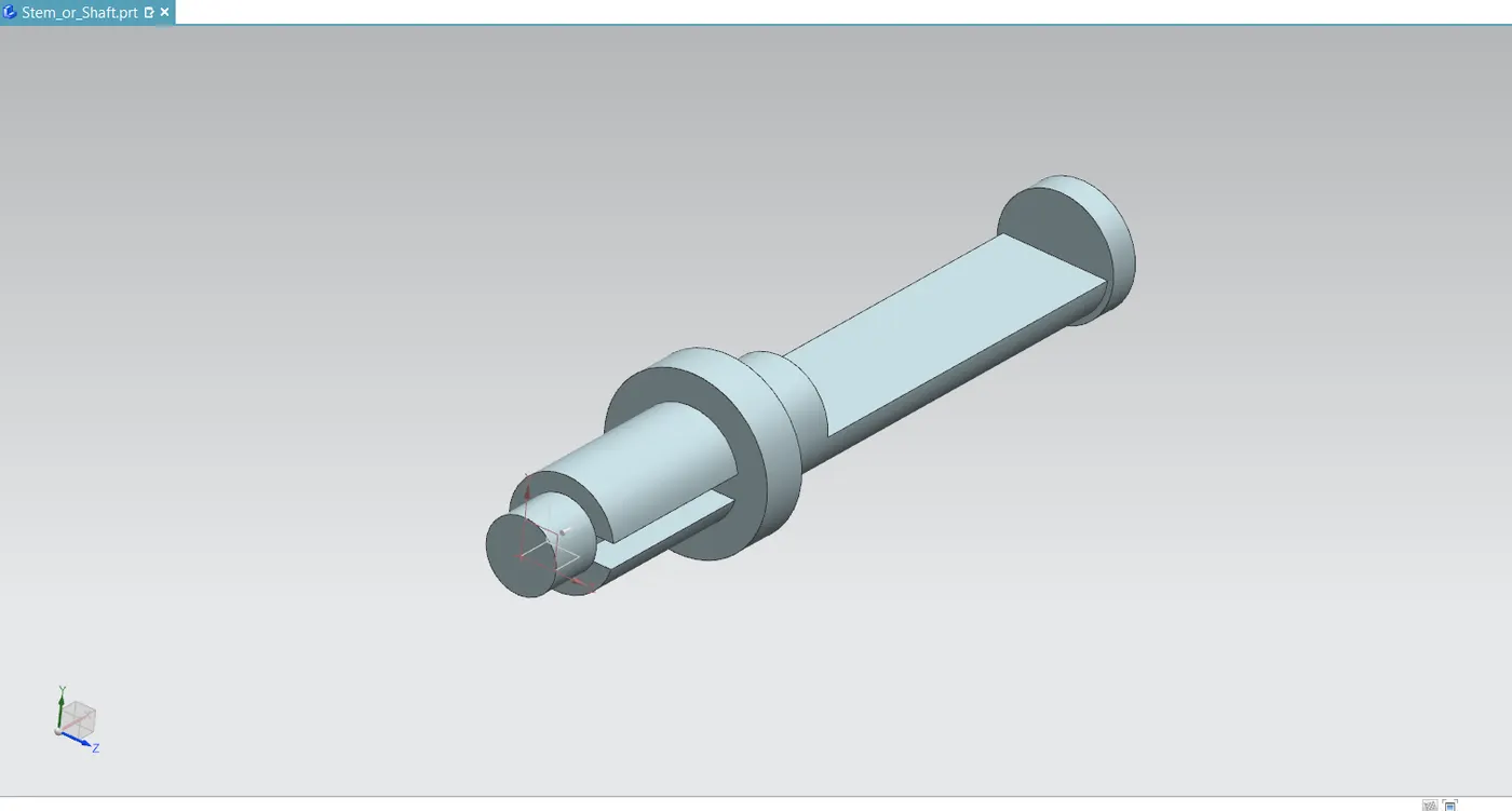
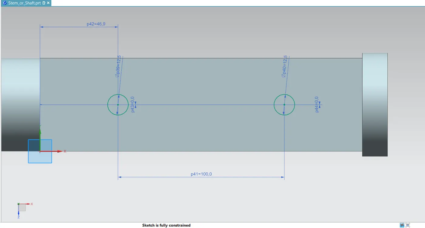
- Next, drill two holes on the larger slot's face for the disc or plate that will be inserted. Next, chamfer the front circular edge for improved handling and security.
Top Flange
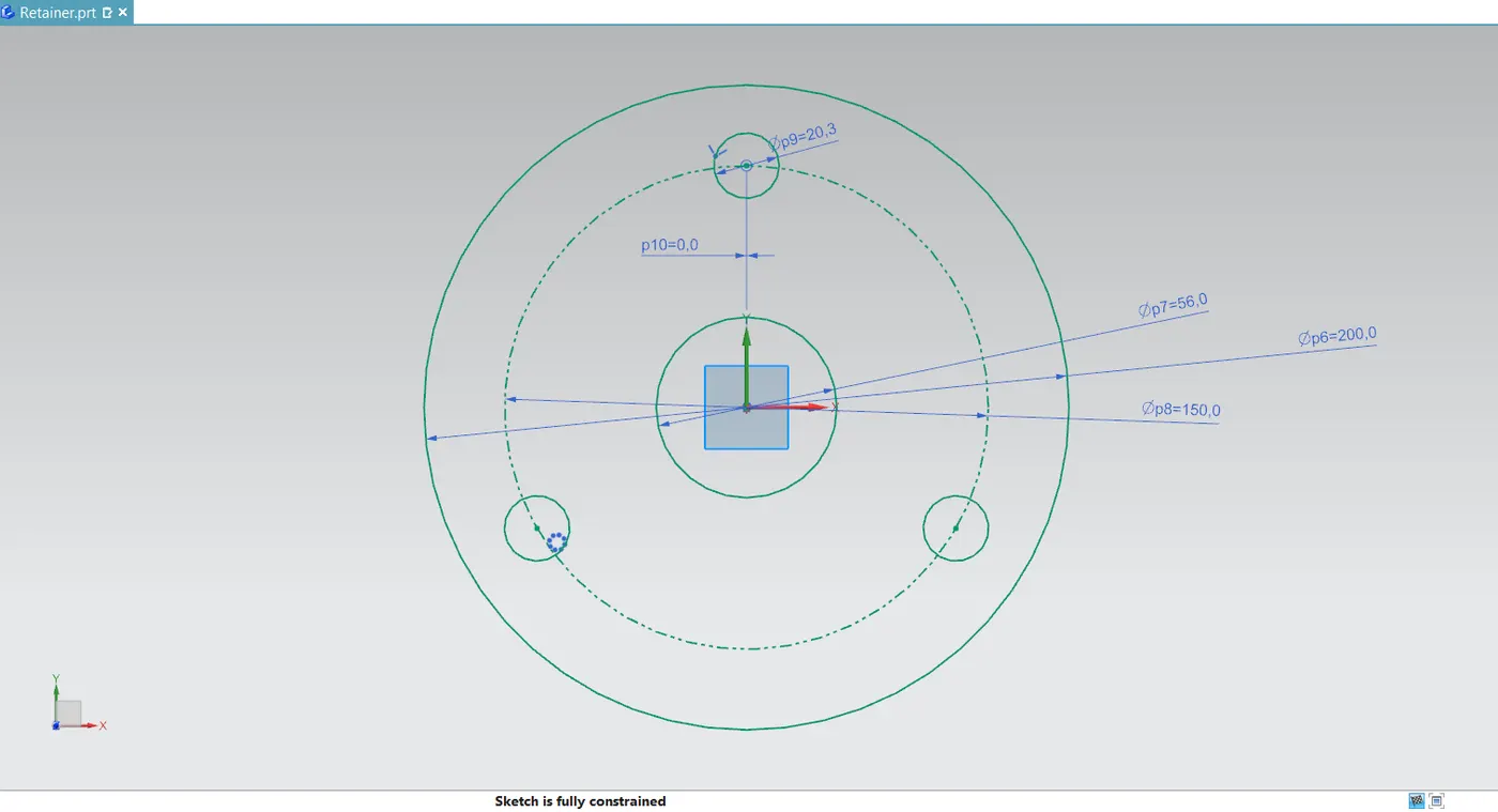
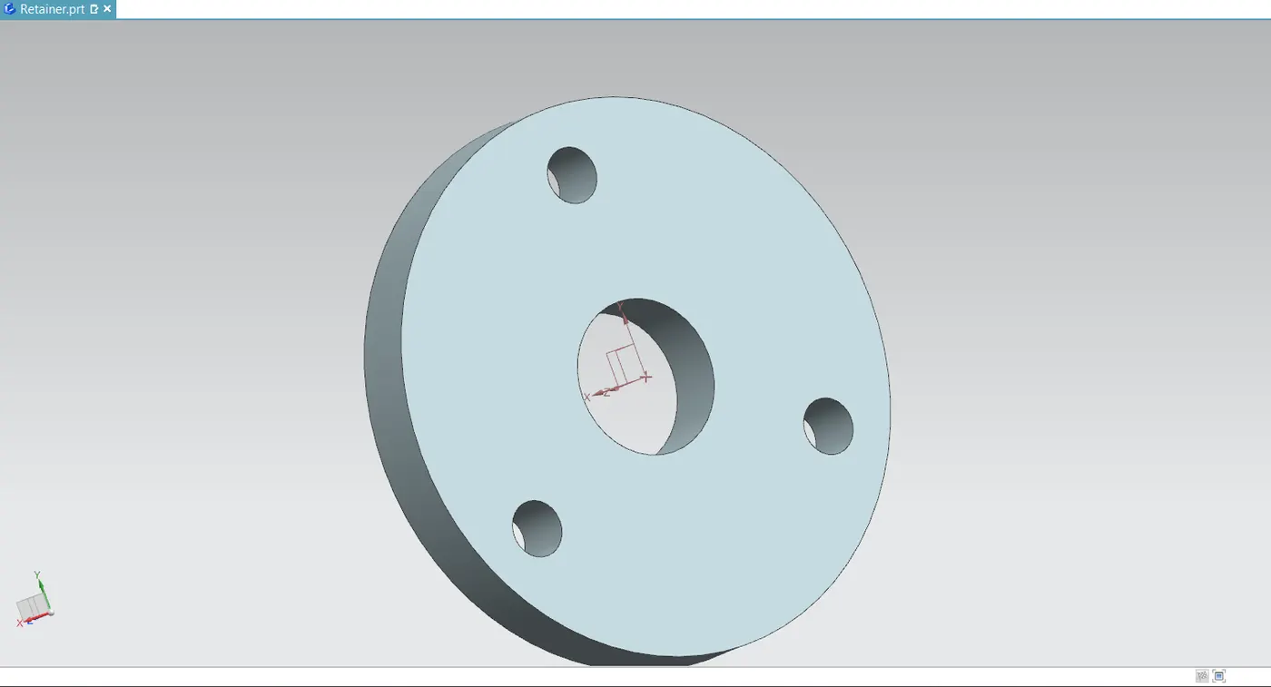
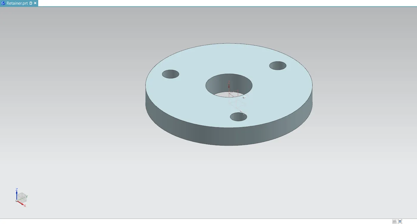
- It is merely a type of washer that is fitted onto the butterfly valve's body.
- Draw a circle with the proper diameter on it and use the extrude command. Additionally, make three holes in the sketch so that we may attach the Retainer/Top Flange to the butterfly valve's part called body.
Disc
- A disc is only the butterfly valve's closure/flow-controlling element that is fastened to the shaft or stem. A ball in a ball valve, a gate in a gate valve, or a plug in a plug valve are the analogous of the disc.
- The butterfly valve can be opened and closed by turning the disc 90 degrees or a quarter of the way.
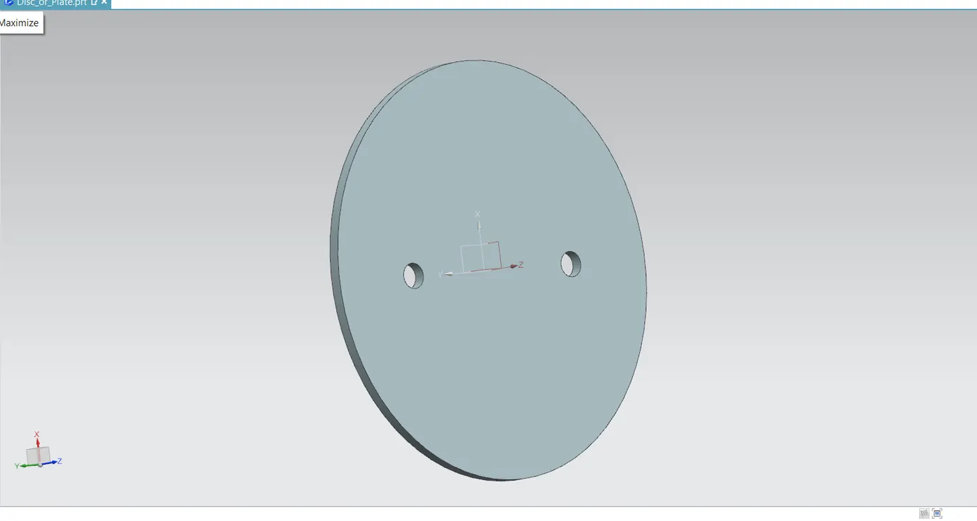
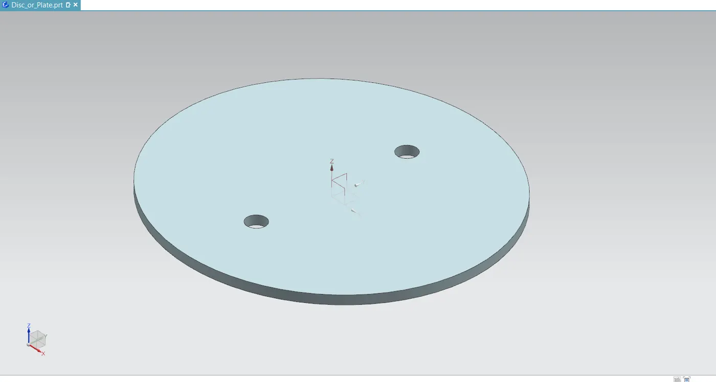
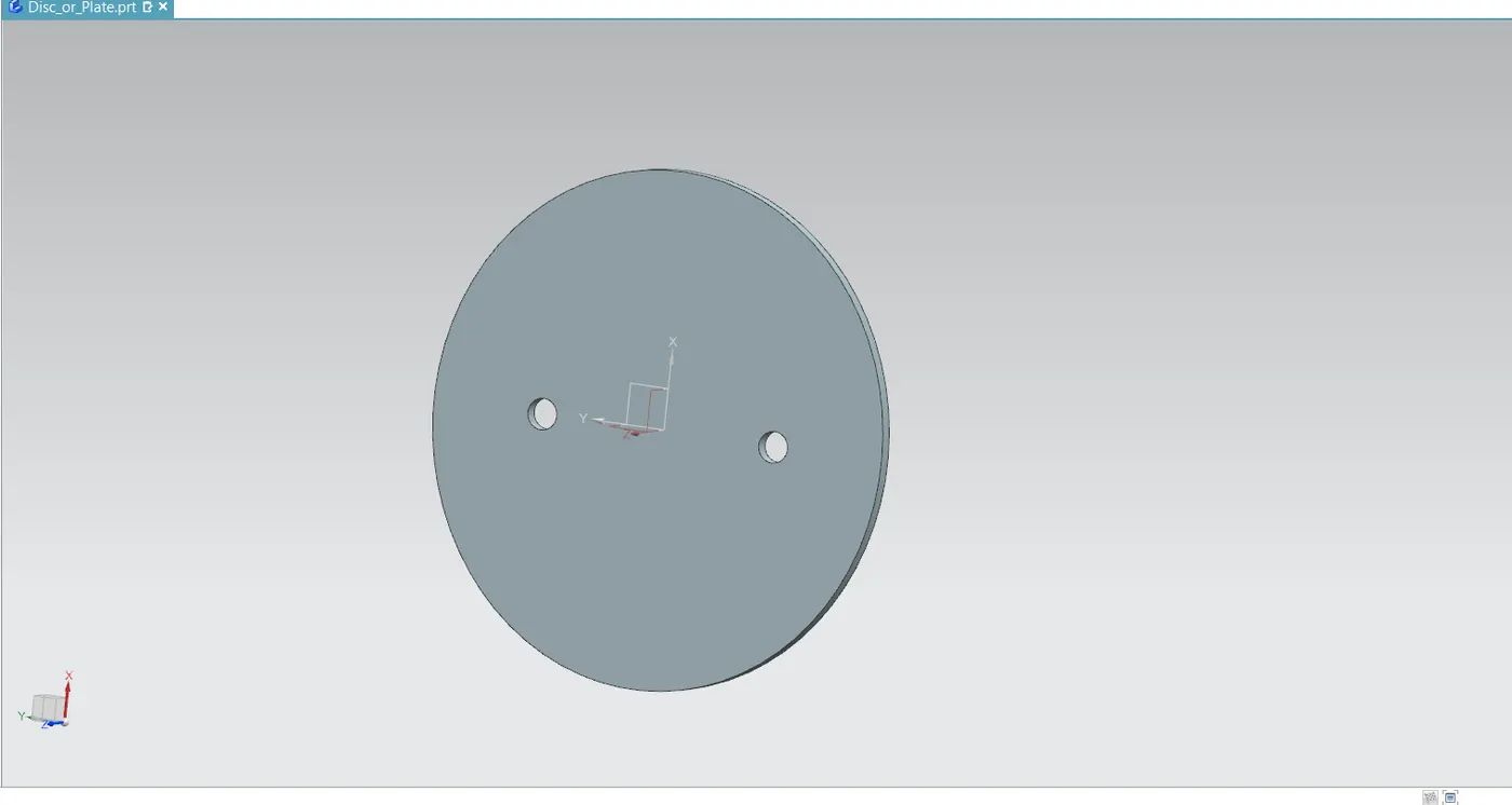
- Draw an ellipse shape with the major and minor distances scaled appropriately. Next, drill two holes along the minor axis so that the disc can be fixed to the shaft.
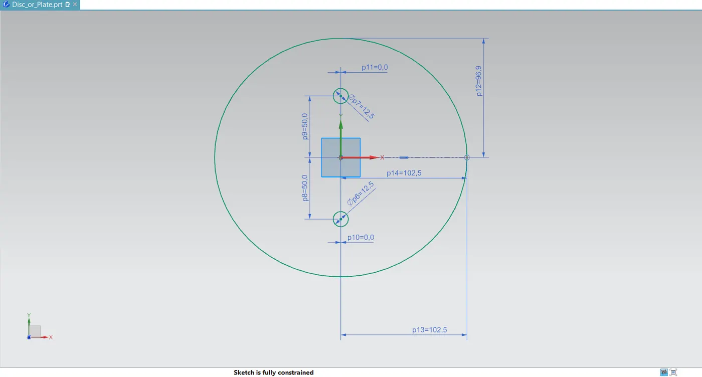
- Extrude the completely limited drawing by giving it the appropriate thickness.
Lever
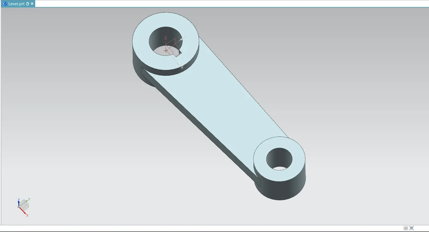
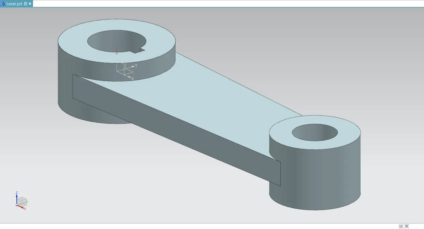
- The lever is fastened above the body and retainer at the shaft/stem's end. This little butterfly valve uses this lever handle. By opening and shutting the disc as needed, we can use this to control the flow.
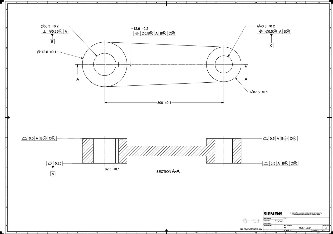
- Draw two circles with the proper diameters and indicate the necessary separation between them. Additionally, in the larger diameter sketch, make a keyway slot. Connect these two drawings by drawing a line that is tangent to each circle.
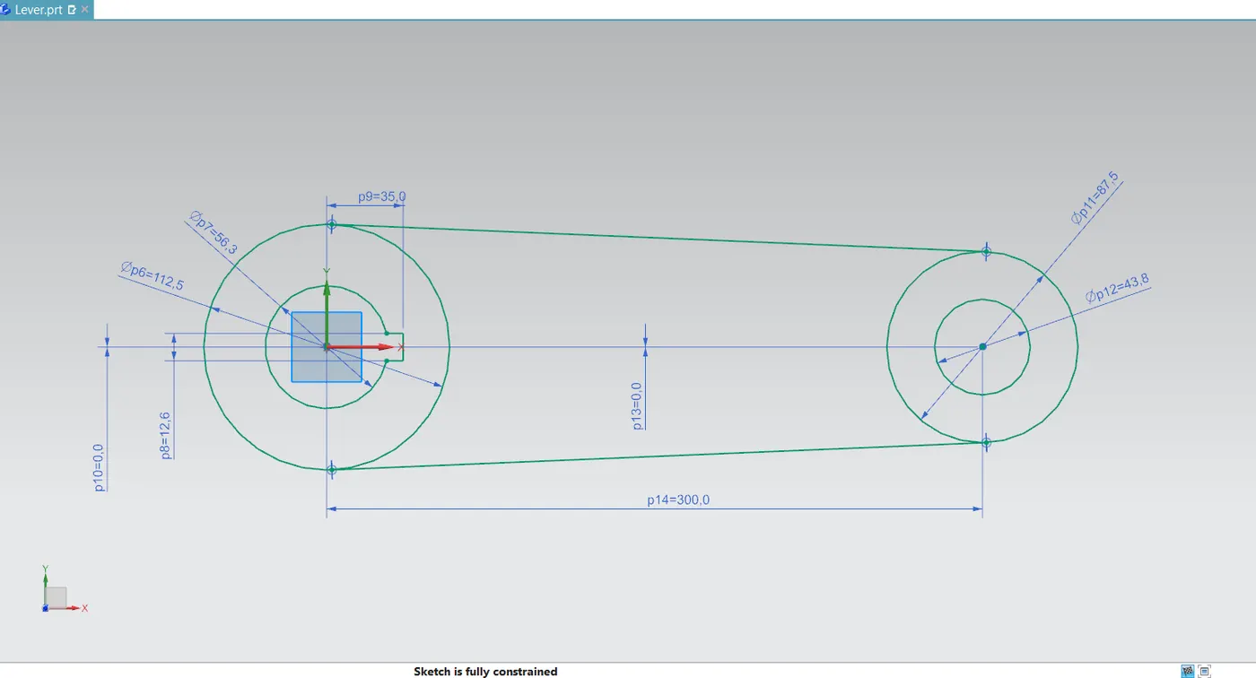
- Once the fully constrained sketch has been created, extrude the circular areas first, followed by the mid-section with varying thickness values.
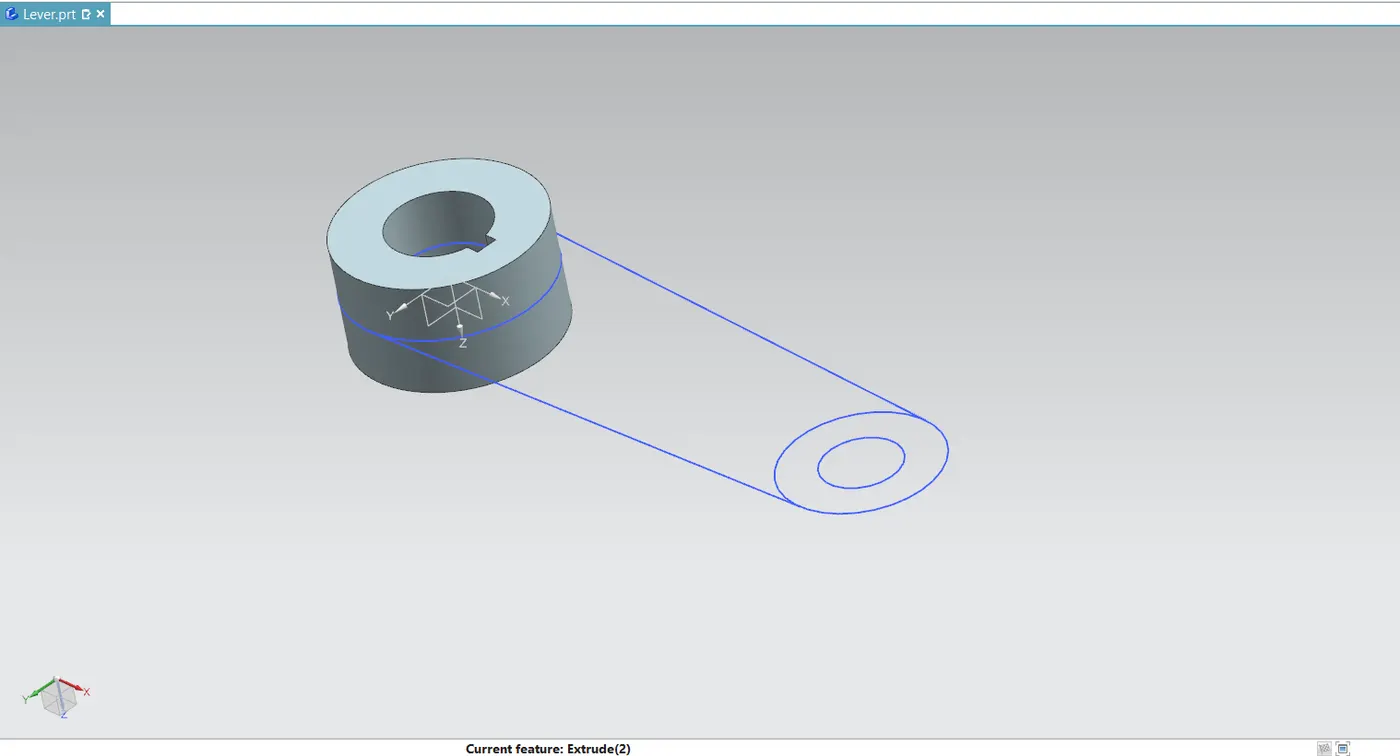
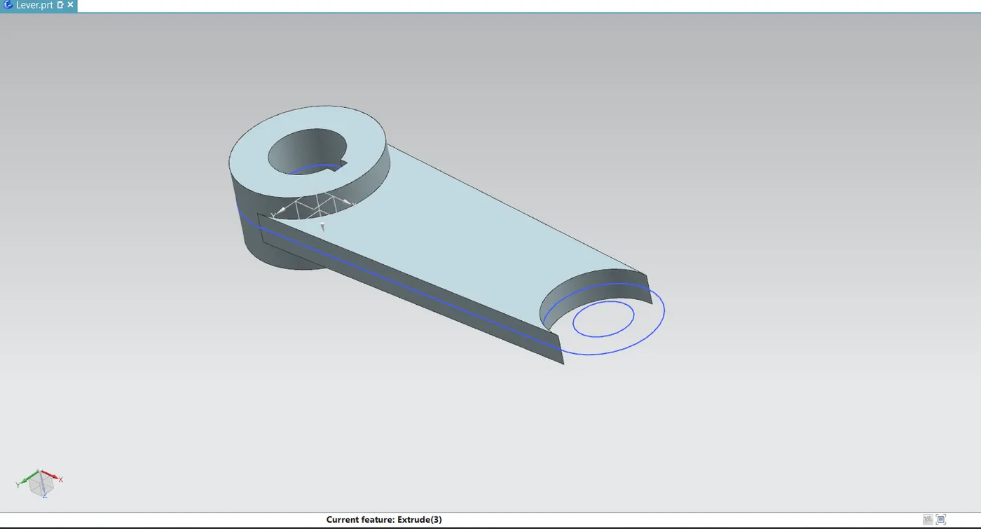
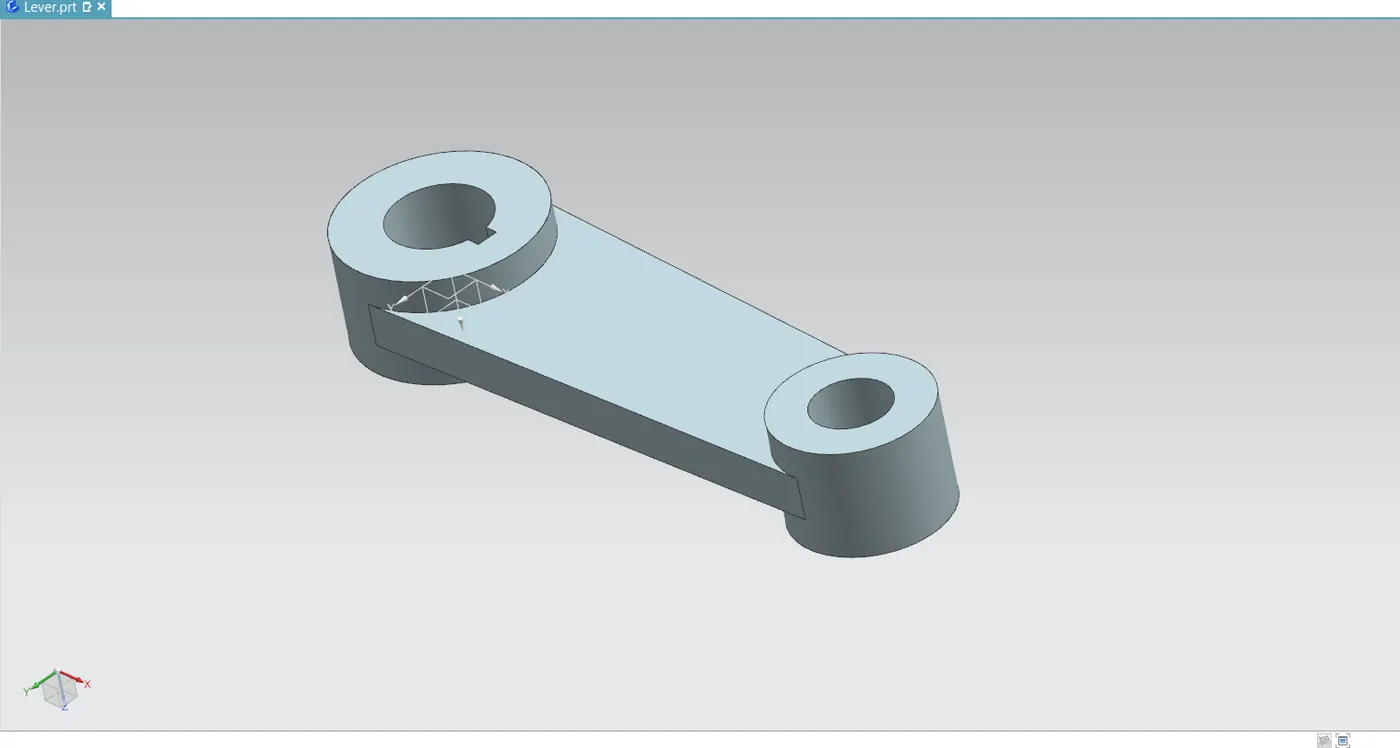
- Then use the unite in Boolean option on the extrude command to integrate every feature. After that, make a design sheet for the model and add GD&T to it.
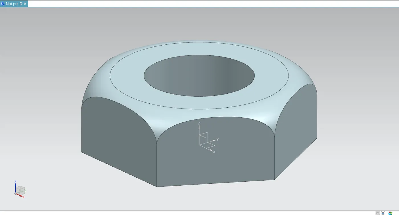
Nut
- It serves to maintain the butterfly valve's body as well as the lever and retainer in place relative to one another.
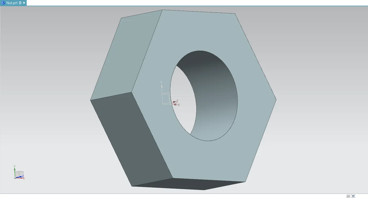
- Make a sketch of a six-sided polygon with the appropriate measurement. To enable it to be put into the shaft, additionally add a circular hole to the sketch.
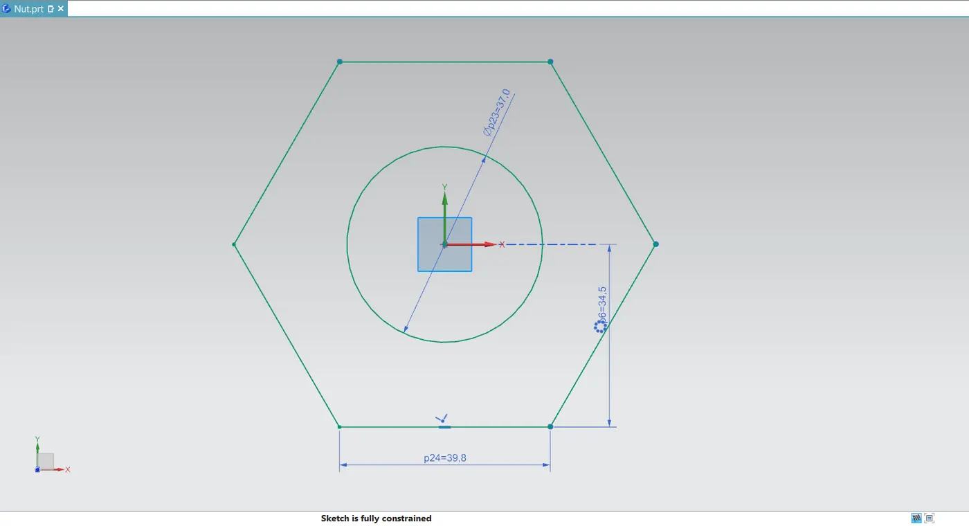
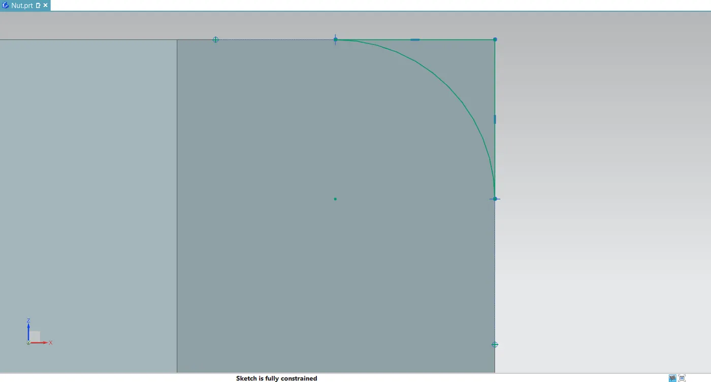
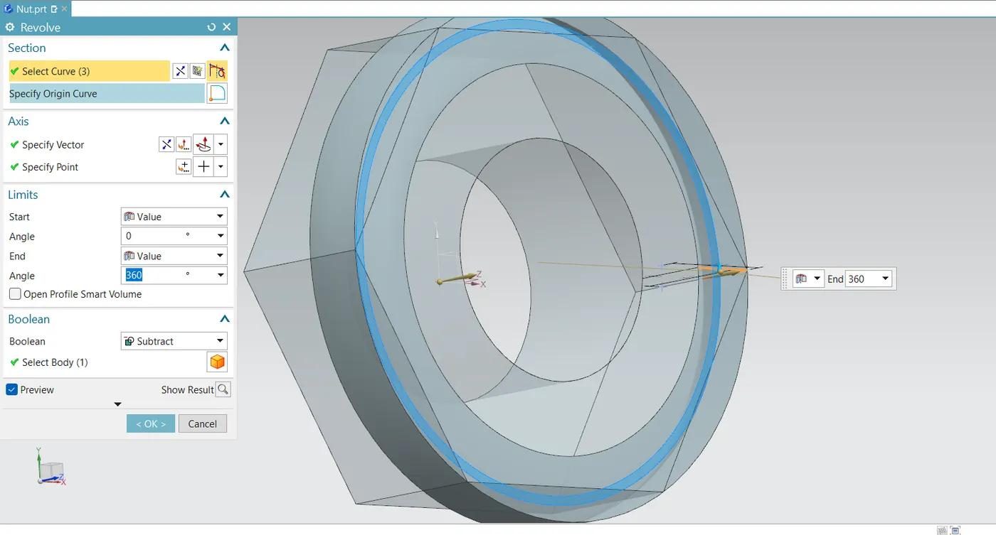
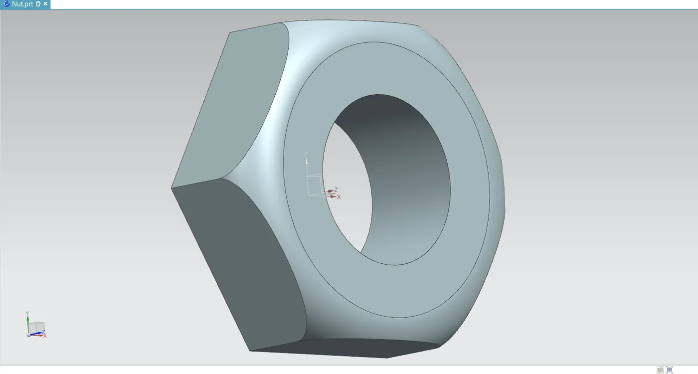
- Add a fillet on the nut's upper edge for handling safety.
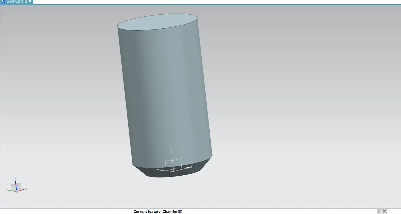
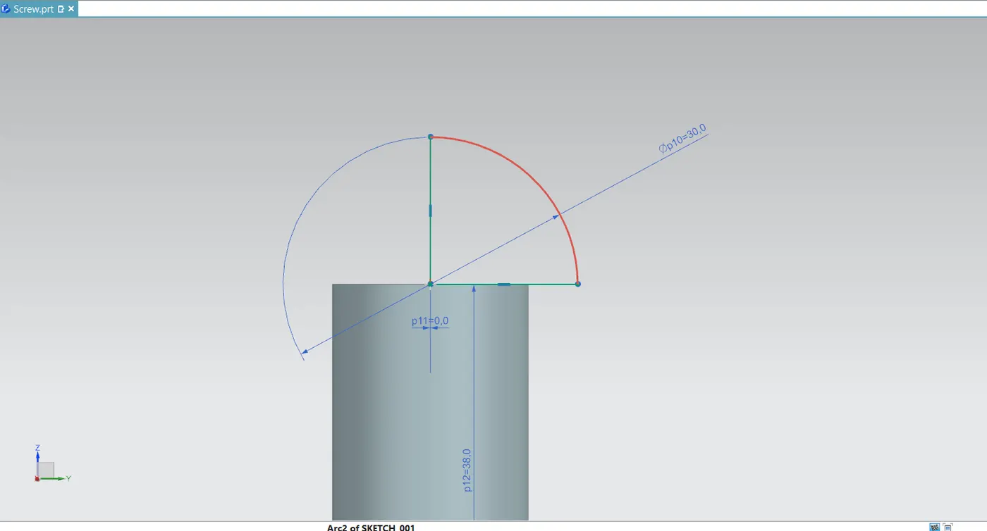
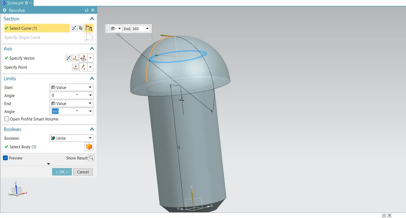
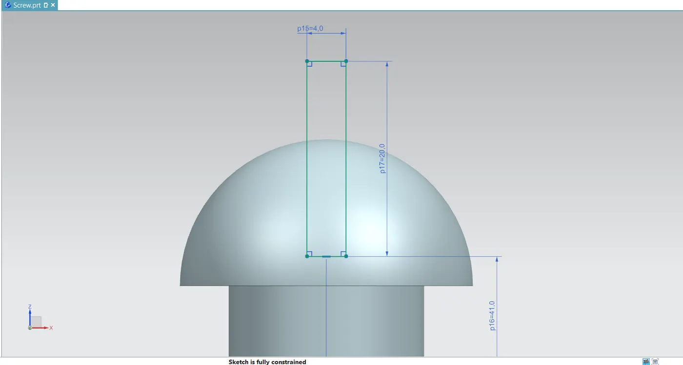
Screw
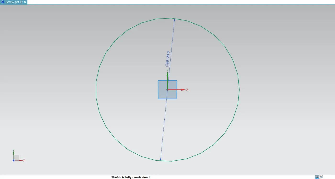
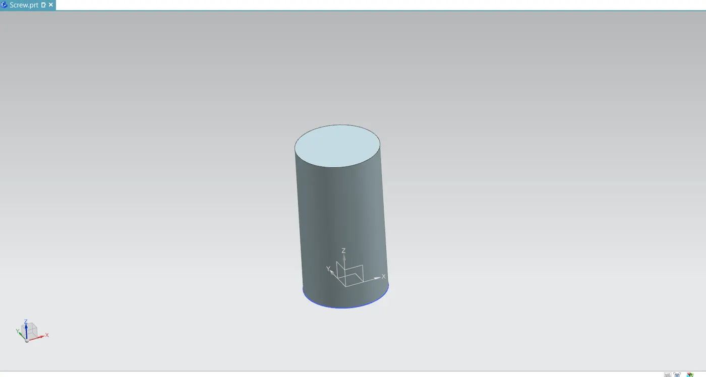
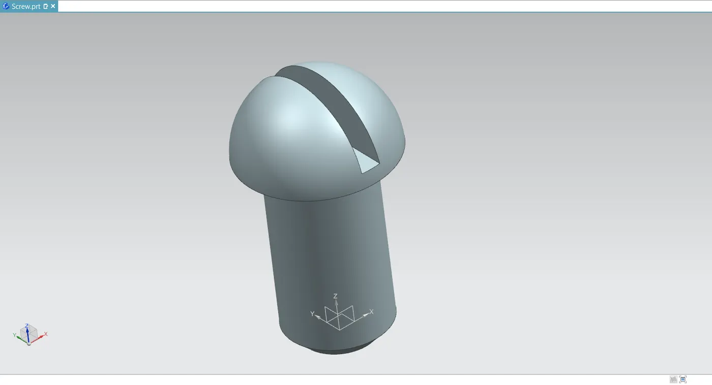
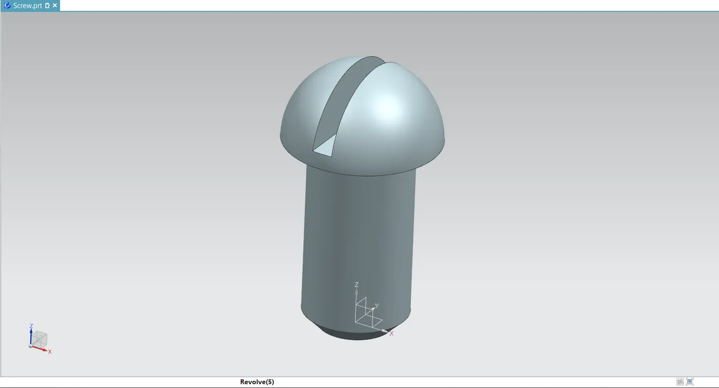
- This screw aids in holding or fixing the butterfly valve's disc to the shaft.
- It holds the shaft in place so that the internal disc of the body may operate properly and prevent it from escaping from the body.
ASSEMBLY OF BUTTERFLY VALVE
- The Add components tool box opens and displays every component that is saved in the necessary location.
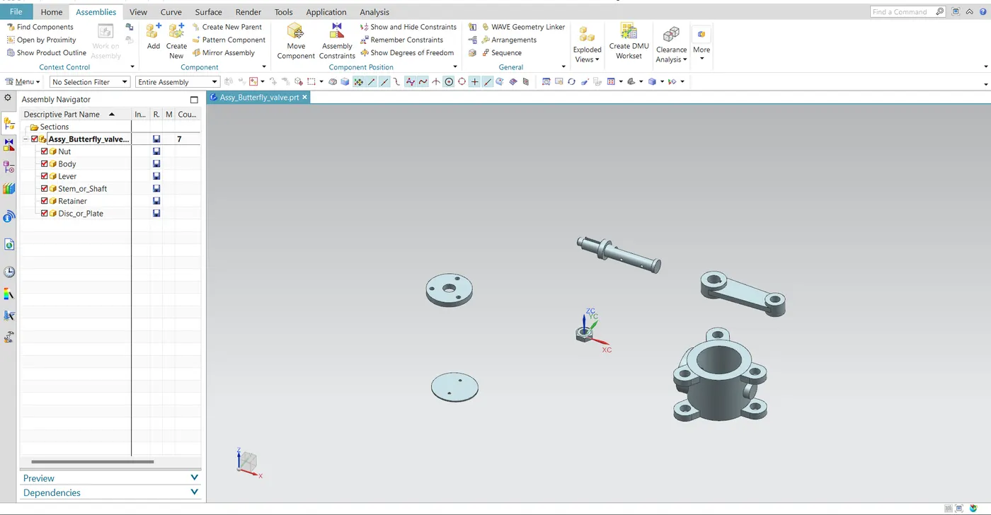
- The various elements are now connected together using the align, touch, infer/axis operations and the move and assembly constraints options.
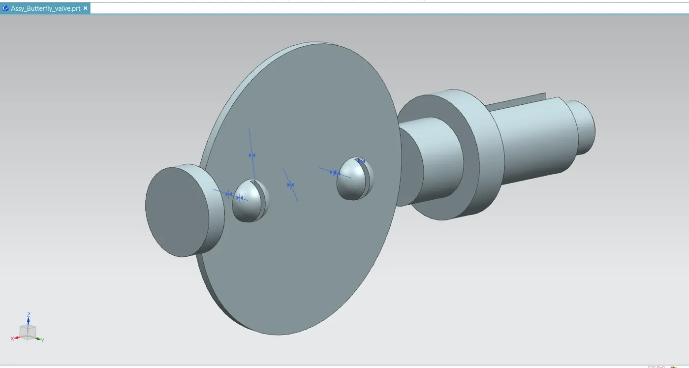
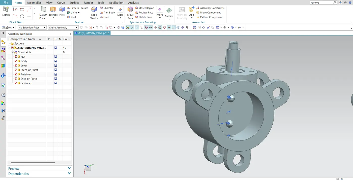
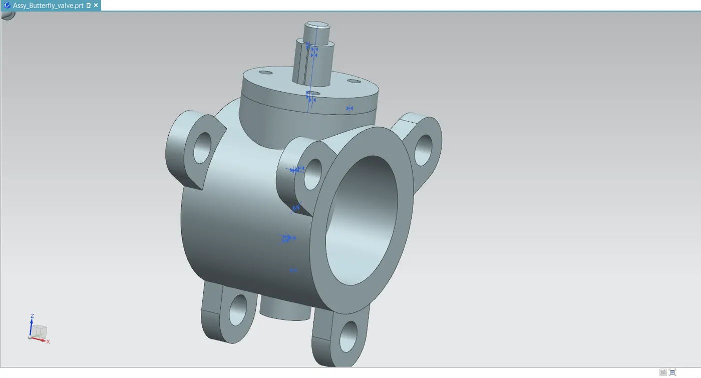
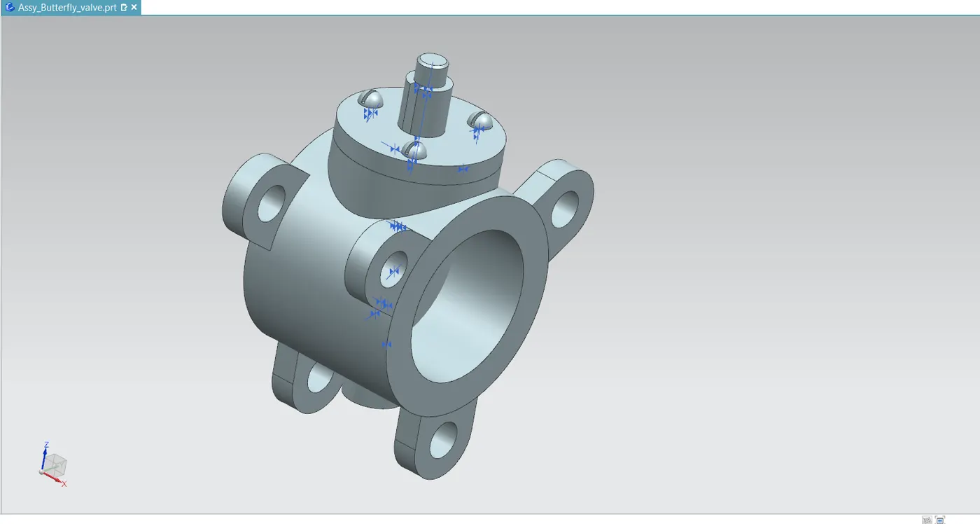
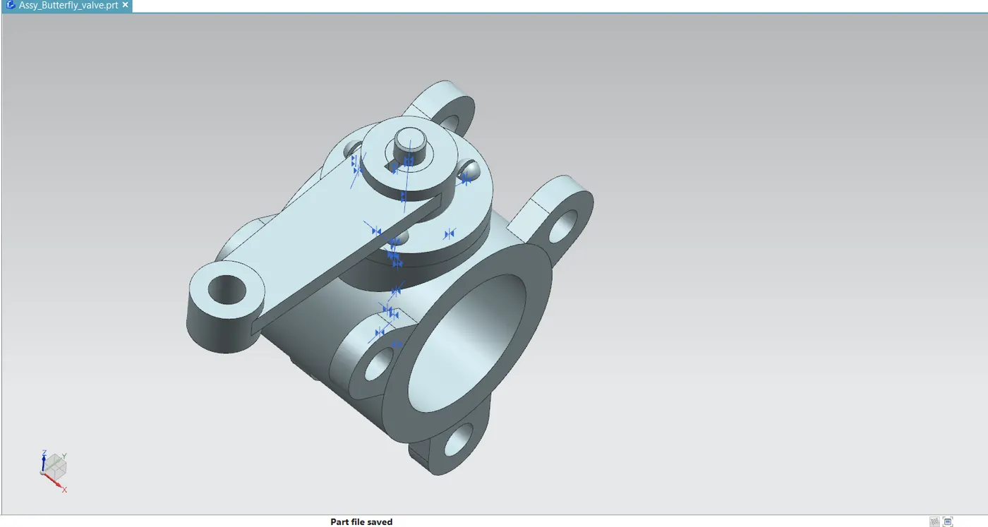
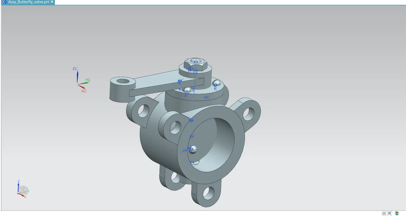
- Lastly, the butterfly valve assembly is stored in the same folder as the other components.
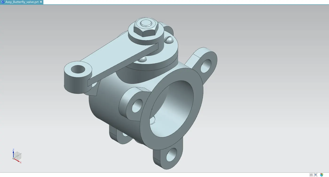
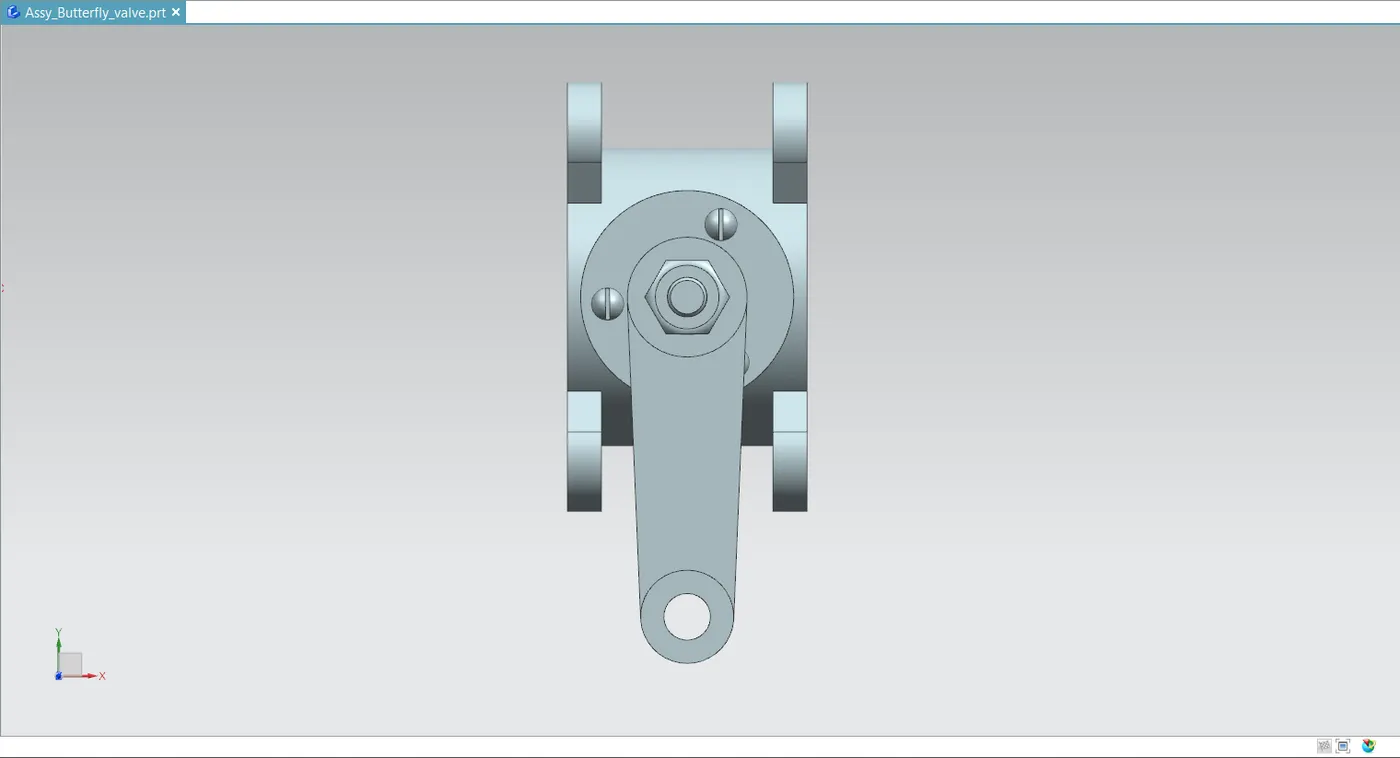
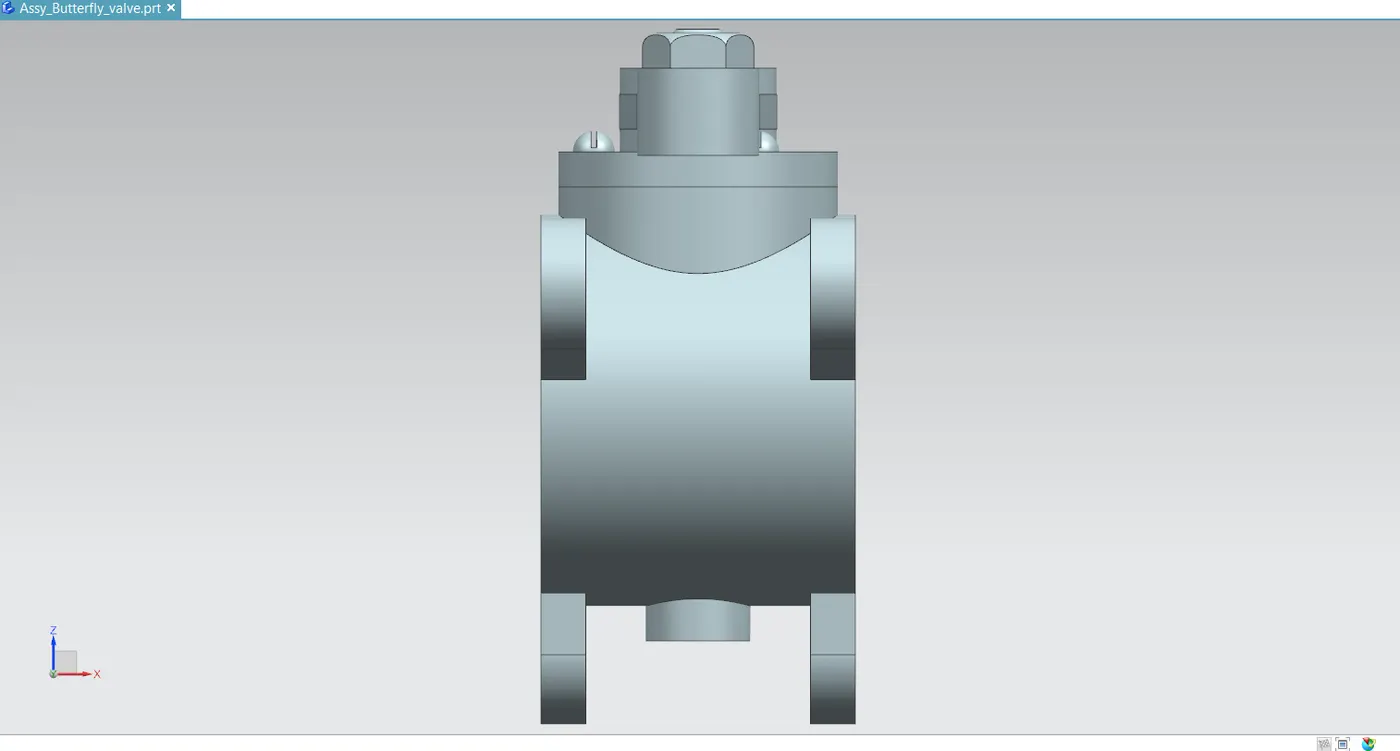
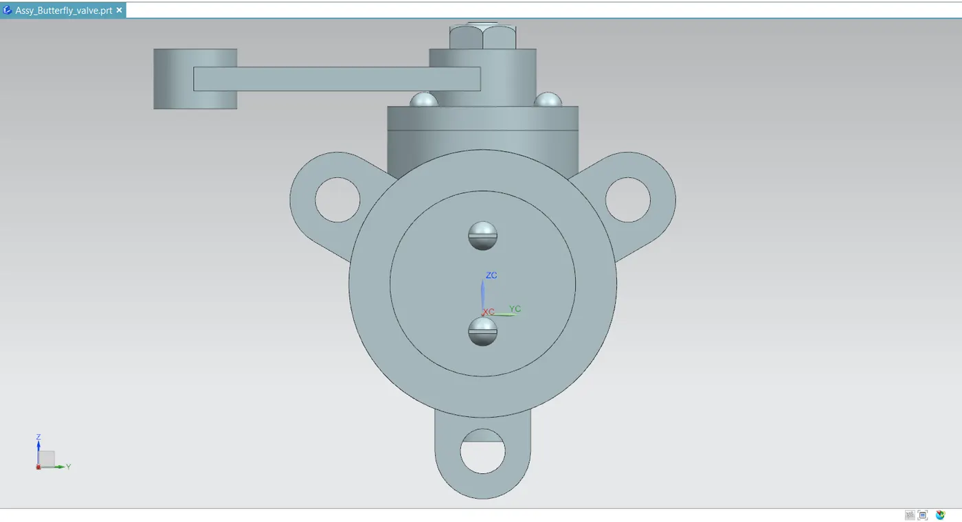
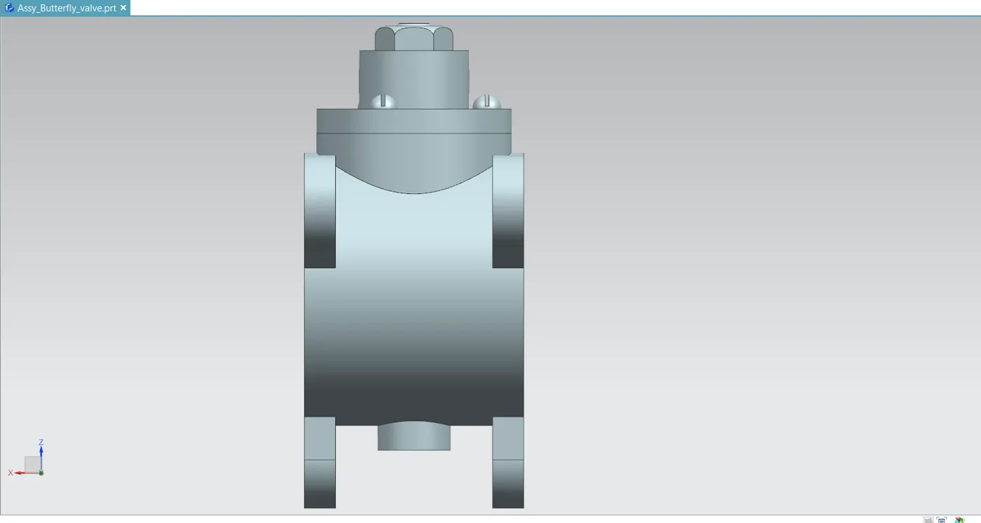
- Finally, drawing is created in drafting application and GD&T symbols are applied to the drawing. Below given images are the different view of the butterfly valve.
CONCLUSION
- As a result, the Siemens NX CAD software is used to construct the butterfly valve and apply geometric dimensioning and tolerance.
- I discovered the importance of GD&T, which describe how it regulates dimensional variation in parts to minimize material waste, lower cost, and do away with the need for some feature inspections. Additionally, since GD&T is a symbol-based language, it facilitates communication between engineers worldwide.
- Additionally, I learnt how to use several stack-up analyses, like MRSS, WC, and RSS, to perform stack/gap analyses. Designed a butterfly valve and gained knowledge of Siemens NX CAD modelling, assembly, and drawing software. Additionally, applied GD&T to the butterfly valve assembly as well as its individual parts.