Week 14 challenge
Topic - Assembly of butterfly valve parts with siemens NX CAD.
Objective - To assemble all the parts of butterfly valve by giving constraints
To make the 2d drawing of the assembly
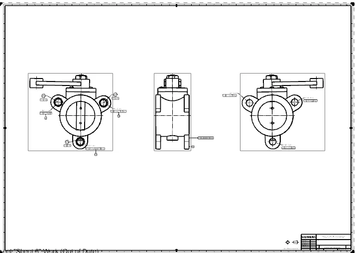
To apply GD&T to the assembled 2d drawing
Introduction
Butterfly valves are a family of quarter-turn rotational motion valves that are used in pipelines to shut-off flow. It is often said that butterfly valves can be used to regulate the flow. However, we do not recommend doing this, as it can damage the valve disk and have a negative effect on the sealing properties. They are used in a wide variety of process media and industries especially in water supply, collection, and distribution, as well as pumping stations, and have a broad range of use cases especially in flow isolation. A couple of their key advantages over other valve families are their simple construction and compactness, resulting in the end products being of lighter weights and lower cost and with smaller installation footprints and faster actuation speeds.
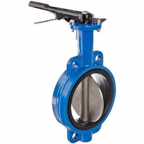
Below are the major butterfly valve components:
- Valve Body
The valve body fits between the pipe flanges - the most common end connection types being flanged, double lug, and wafer types.
- Disc
Attached to the valve body is the disc that functions as a gate that stops or throttles fluid flow; it can be considered equivalent to a gate in a gate valve, or a ball in a ball valve. The disc is typically bored to receive the stem, or shaft. There are many variations in disc design, orientation, and material in order to improve flow, sealing, and/or operating torque.
- Seat
Lining the internal valve body is a strong elastomer or metal anti-leak seal that secures the disc in place in the closed position in order to achieve complete shutoff. The 9881k series’ stainless steel weld filled and microfinished integral body seat ensures a corrosion and erosion resistant seat face. With this special type of seat design, it is possible to manufacture the valve drop tight according to EN12266 –A requirements.
- Stem
The valve shaft, often also referred to as the stem, is the component that connects the disc to the actuation mechanism and transmits the torque through itself.
- Seals
Seals are present at multiple interfaces within the valve to either ensure a tight seal during operation or to isolate the process media from the valve’s internal components for a more flexible and cost-efficient design.
Advantages of GD&T
- Simple communication. GD&T allows you to convey substantial information about your part’s design using a relatively small amount of letters, numbers, and symbols. No long paragraphs of explanation necessary! The ability to communicate efficiently reduces back and forth between you and the contract manufacturing service you are working with.
- Accurate production. Since GD&T is such a precisely articulated system of language, it minimizes ambiguity in the description of a parts design. As a result, you can be confident that your part will be manufactured with the highest degree of accuracy and work as intended in the field.
- Known tolerances. GD&T gives manufacturers a clear understanding of the tolerances for a specific part. It provides the maximum amount of tolerance for the part to function properly, which reduces part complexity so that you aren’t overspending for a minimum tolerance that you may not need.
- Universal language. You may find yourself in a situation where you want to work with a contract machining company in another country with a spoken language that is different from yours. Great news! GD&T is a universal language widely accepted across the world, thereby eliminating frustrating language barriers for overseas production.
- Precise assemblies. If you have two mating parts that need to come together in an assembly, GD&T is an excellent way to communicate how this interfacing can best take place. In these situations, GD&T clearly depicts the tolerances of each part so that manufacturers can easily tell if a measurement is off and adjust accordingly.
Different views of butterfly valve assembly
FRONT VIEW
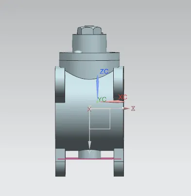
LEFT SIDE VIEW
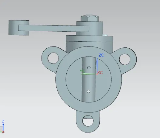
RIGHT SIDE VIEW
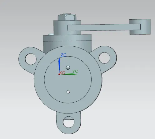
TOP VIEW
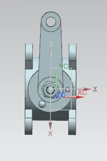
BOTTOM VIEW
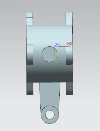
ISOMETRIC VIEW
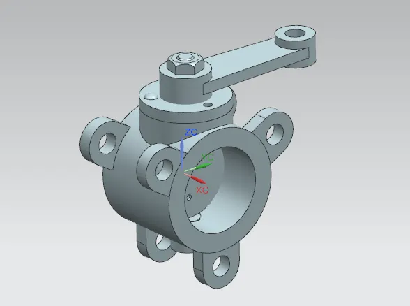
CONSTRAINTS ADDED TO ASSEMBLY
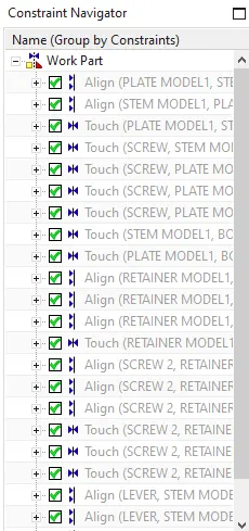
2D DRAWING WITH GD&T
Conclusion
We have succesfully modeled assembled and drafted the butterfly valve and applied GD&T to the assembly