Week 14 challenge
AIM : The objective of this project is to design a butterfly valve and apply GD&T to it's components and final assembly using Siemens NX.
INTRODUCTION
A butterfly valve is from a family of valves called Quarter turn-valves. In operation, the valve is fully open or closed when the disc is rotated a quarter turn. The "butterfly" is a metal disc mounted on a rod. When the valve is closed, the disc is turned so that it completely blocks off the passageway. When the valve is fully open, the disc is rotated a quarter turn so that it allows an almost unrestricted passage of the fluid. The valve may also be opened incrementally to throttle flow.
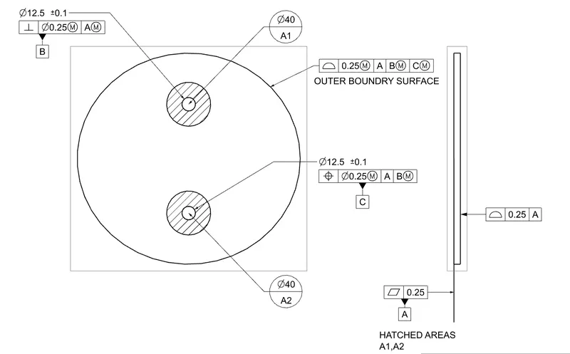
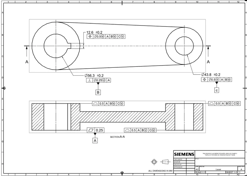
Here after modelling various components of the Butterfly valve, GD&T (Geometric Dimensioning & Tolerancing) is applied to each component and final assembly.Geometric Dimensioning and Tolerancing (GD&T) is a system for defining and communicating engineering tolerances. It uses a symbolic language on engineering drawings and computer-generated three-dimensional solid models that explicitly describe nominal geometry and its allowable variation. It tells the manufacturing staff and machines what degree of accuracy and precision is needed on each controlled feature of the part. GD&T is used to define the nominal (theoretically perfect) geometry of parts and assemblies, to define the allowable variation in form and possible size of individual features, and to define the allowable variation between features.
COMPONENTS OF BUTTERFLY VALVE
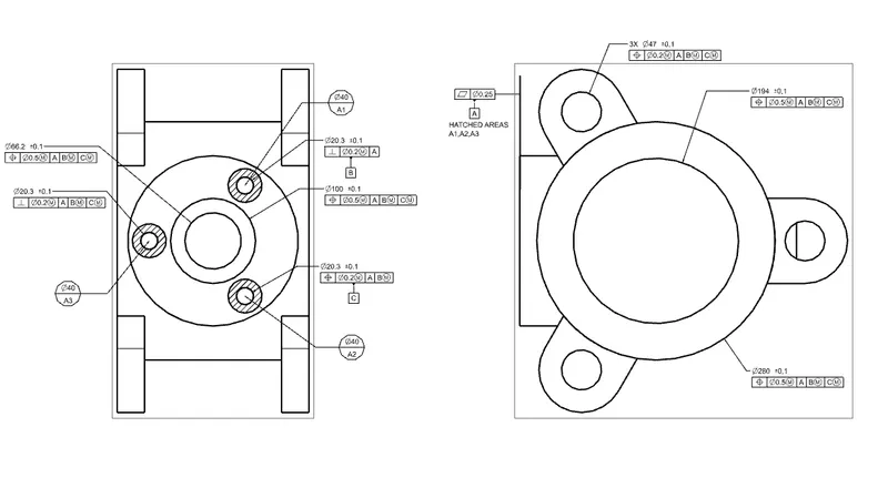
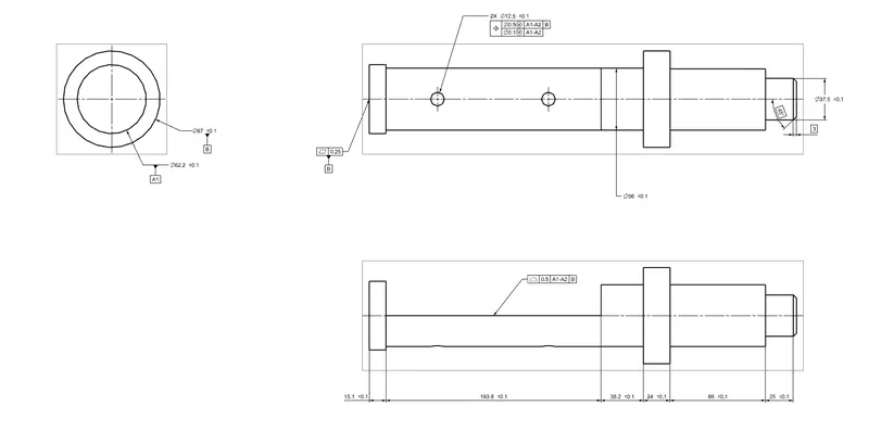
Various components of the butterfly valve have been designed, and GD&T is applied to the drawing sheets. The following details are given below
BODY - BUTTERFLY VALVE
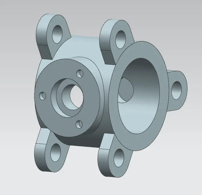
Butterfly valves generally have bodies that fit between two pipe flanges. This butterfly valve has a lug body design consisting of protruding lugs that provide bolt holes matching those in the pipe flange.Create two circles of required diameter and use Extrude command to form a cylindrical body/housing. On that cylindrical body create three lugs with holes in them. This will help us connect the butterfly valve to the pipe flanges. We have created the lugs on the mid-plane and then Extruded them with reference to the mid-plane(i.e. symmetrical value). Using the Move object command we created similar lugs on the outer surfaces of the body with the help of lugs created earlier.
2. SHAFT - BUTTERFLY VALVE
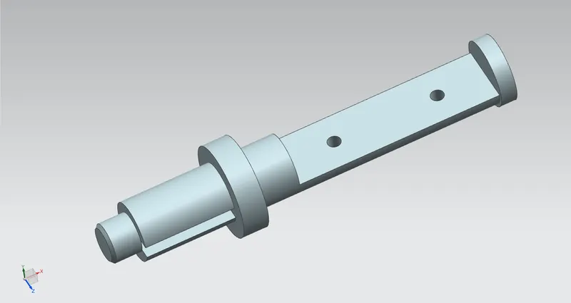
In order for the disk to be held in the proper position, the stem must extend beyond the bottom of the disk and fit into a bushing in the bottom of the valve body. One or two similar bushings are along the upper portion of the stem as well.
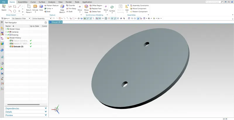
3. DISC - BUTTERFLY VALVE
When valve is fully opened or closed the disc is rotated a quarter turn.Disc is mounted on shaft. When the valve is closed, the disc is turned so that it completely blocks off the passageway.When the valve is fully open, the disc is rotated a quarter turn so that it allows an almost unrestricted passage of the fluid.
4. LEVER - BUTTERFLY VALVE
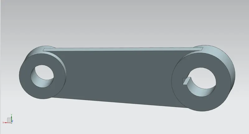
The hand lever is commonly used for small butterfly valves and is used to open and closed the valve. It is capable of being locked into a position of open, partially open, or closed.
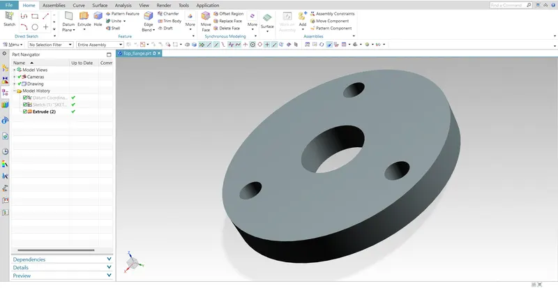
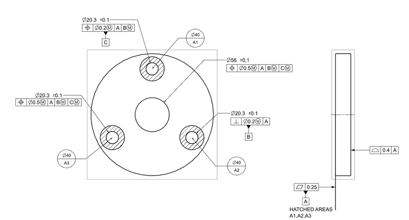
5. RETAINER - BUTTERFLY VALVE
Butterfly valves comprise a valve seat comprising a generally S-shaped cross-section and a valve seat retainer configured with appropriately shaped cooperating surfaces.Soft Seated (PTFE/RTFE) – a synthetic fluoropolymer that is highly resistant to chemicals as compared with other plastics. Plus, PTFE lined seat has a low coefficient of friction which makes it ideal for low torque applications. Metal-to-metal (SS316 and Inconel) – Inconel butterfly valves are used for applications requiring heavy-duty seats such as in handling bulkier fluids. On the other hand, Stainless steel butterfly valves can be used in processing corrosivsubstances as they have a higher resistance to corrosion than Inconel.
6. NUT - BUTTERFLY VALVE
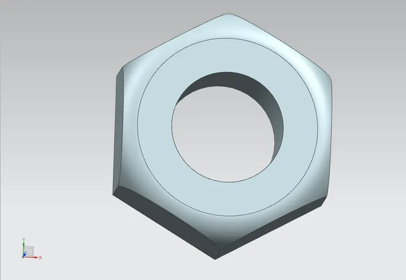
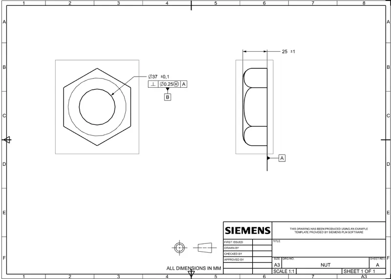
Nuts are almost always used in conjunction with a mating bolt to fasten multiple parts together. The two partners are kept together by a combination of their threads' friction.
ASSEMBLY - BUTTERFLY VALVE
After modeling all the individual parts of the butterfly valve, all parts are assembled together in the assembly workbench of NX.
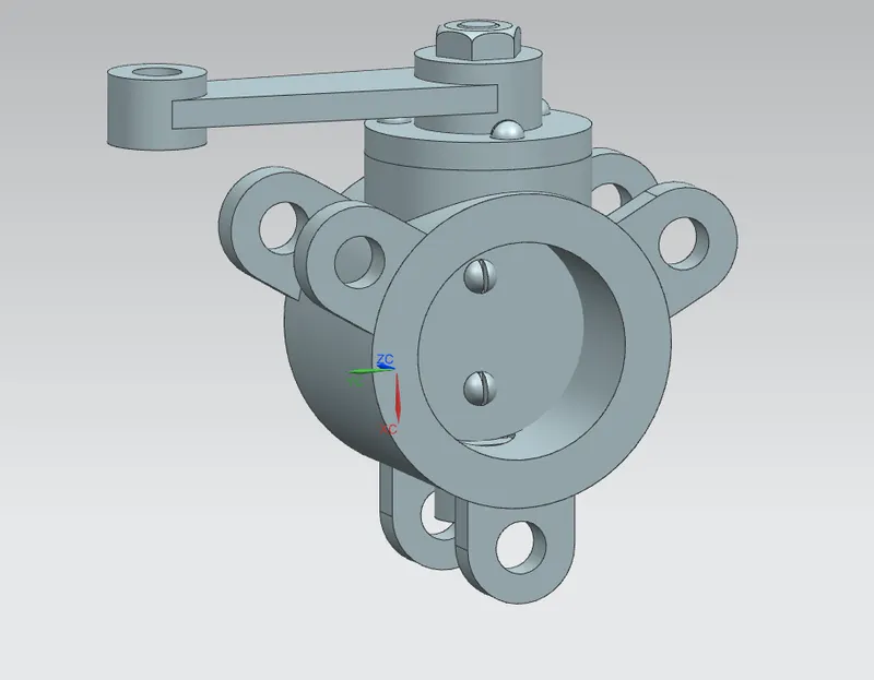
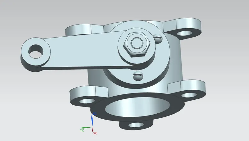
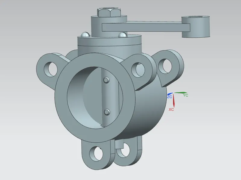
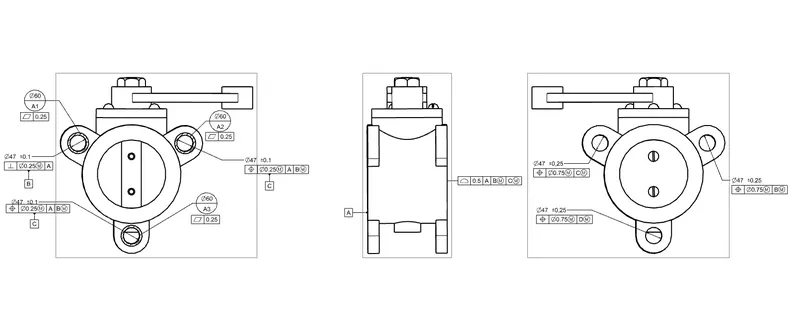
CONCLUSION: Therefore,the Butterfly valve is created and the Geometric Dimensioning and tolerances are applied with the help of using NX-12 software.