Week 14 challenge
Aim:
To Assemble the Butter fly valve by using the sub parts created and apply Gd&T to the Butter fly valve assembly drawing .
Introduction:
- A Butter fly valve is a valve that isolates or regulates the flow of a fluid .The closing mechanism is a disk that rotates .A buterfly valve is form a family of valves called quarter turn valves .
In operation the valve is fully open or closed when the disc is rotated a quarter turn. - The Butter fly is a metal disc mounted on a rod when the valve is closed the disc is turned so that it completely blocks off the passageway .Whenthe valve is fully open , the disc is rotated a quarter turn so that it allows an almost unrestricted passage of the fluid .The valve may also be opened incrementally to throttle flow .
Geometric Dimensioning and Tolerancing(GD&T):
Geometric Dimensioning and Tolerancing is a system for defining and communicating engineering tolerance .It uses symbolic language an engineering drawings and computer generated three dimensional solid metals that explicity describe nominal geometry and its allowable variation.It tells the manufacturing staff and machines what degree of accuracy and precision is needed on each controlled feature of the part. GD&T is used to define the nominal (theoritically perfect) geometry of parts and assemblies , to define the allowable variation in form and possible size of individual features, and to define the allowable variation between the features .There are several standards available worldwide that describes the symbols and define the rules in GD&T .One such standard is the american society of Mechanical Engineers(ASME) Y14.5
Parts of the Butter fly Valve Assembly:
- Butter Fly Valve Body
- Stem
- Retainer Plate
- Disc
- Lever Handle
- Nut
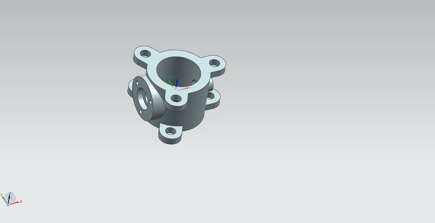
Butterfly Valve Body:
- The Body is the housing for the internal components it is the main part of the Butterfly valve body.The body connects to two pipes and its two sides and it regulates the flow For the creation of the simple feature part like extrude , move objects are used in the modelling application of NX.The image was shown below.
Stem:
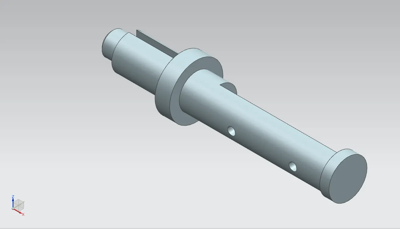
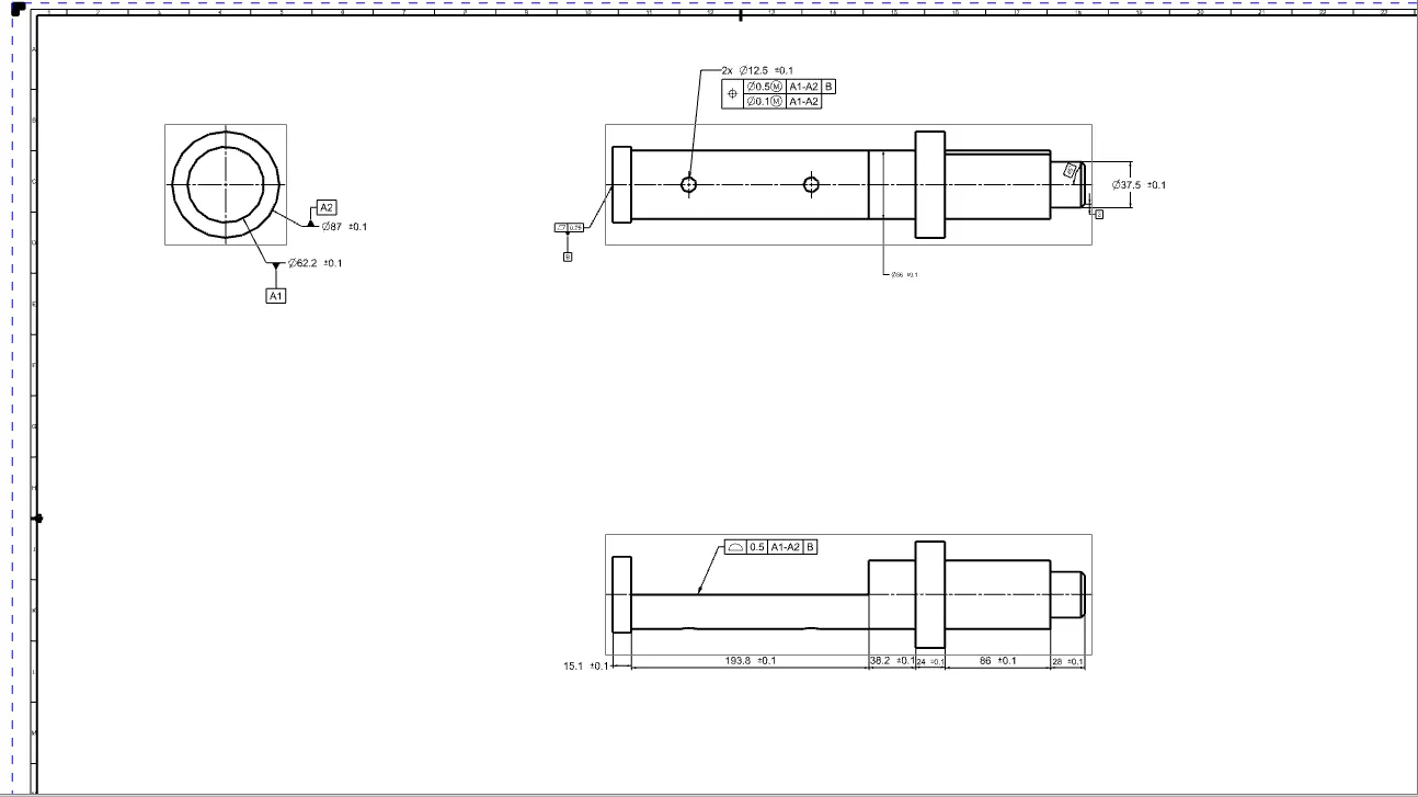
- It is another important part of the component of the butter fly valve .It inserts into the body of the valve and sits perpendicular to the direction of the flow .It holds the disc inside the body and is clamped with the lever outside the body .It is created using simple features like revolve and extrude features in the NX modelling environment.The image of the stem is shown below
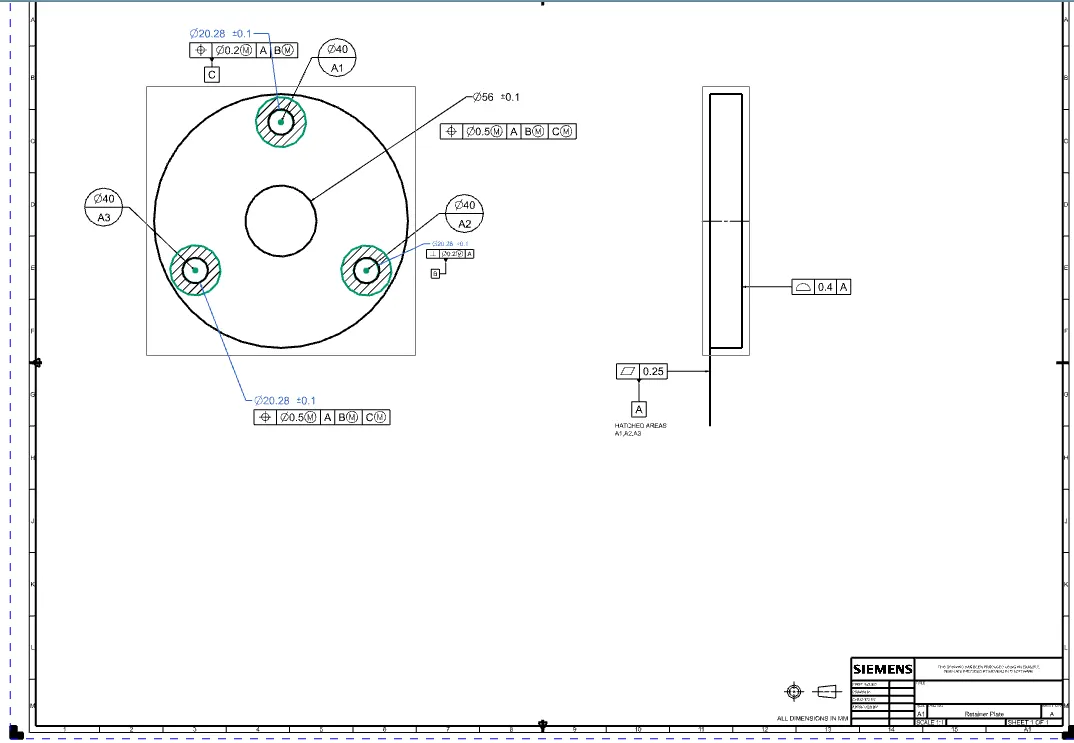
GD&T applied Drawing of Stem:
Retainer Plate:
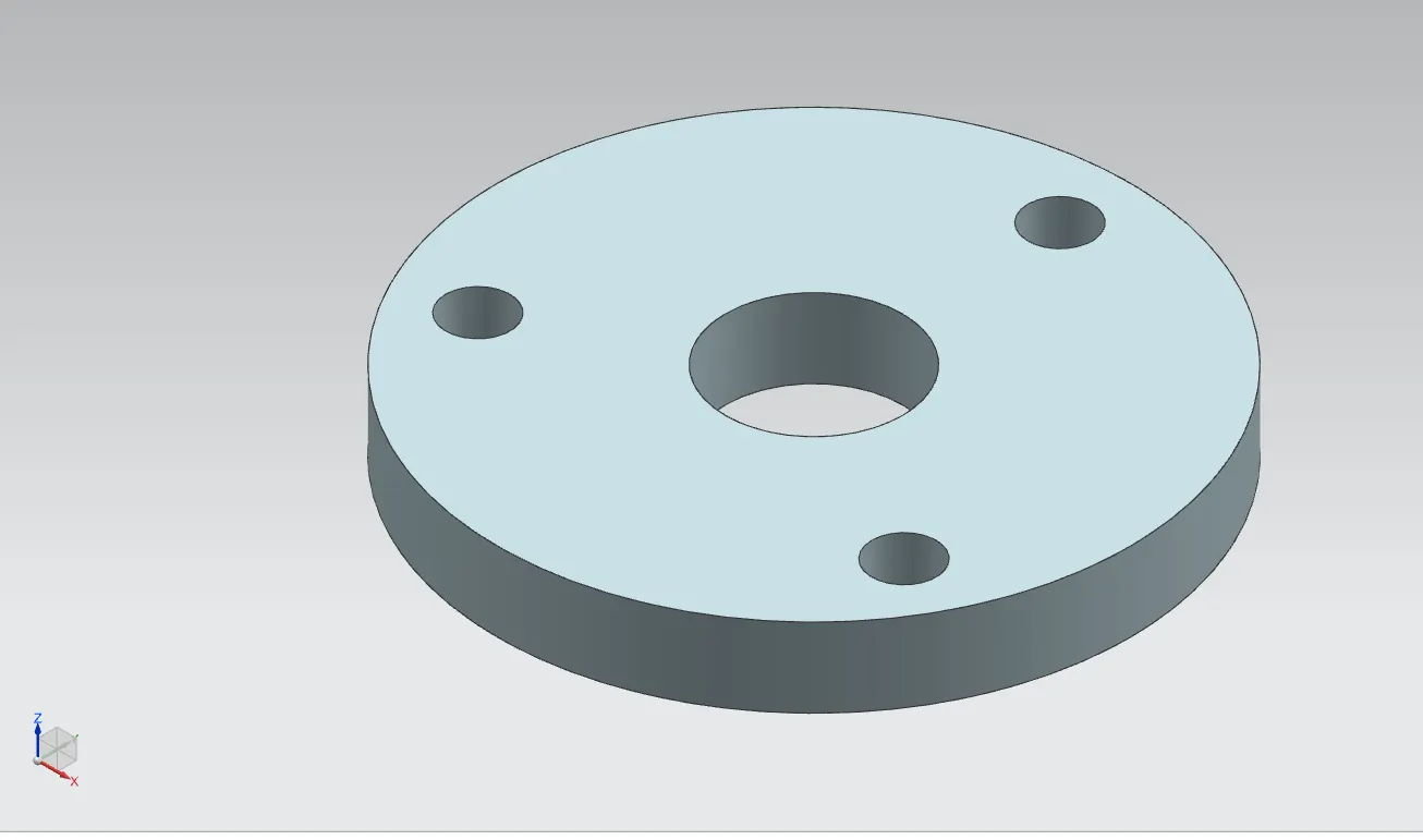
- This parts helps to retain or fix the shaft with the body of the butterfly valve .It prevents the stem fron coming out of the body and keeps it in position for the proper functioning of the disc inside the body .
- The creation of the retainer plate involves only a simple feature like extrude on NX .The image of Retainer is shown below.
GD&T applied Drawing of Retainer:
Disc:
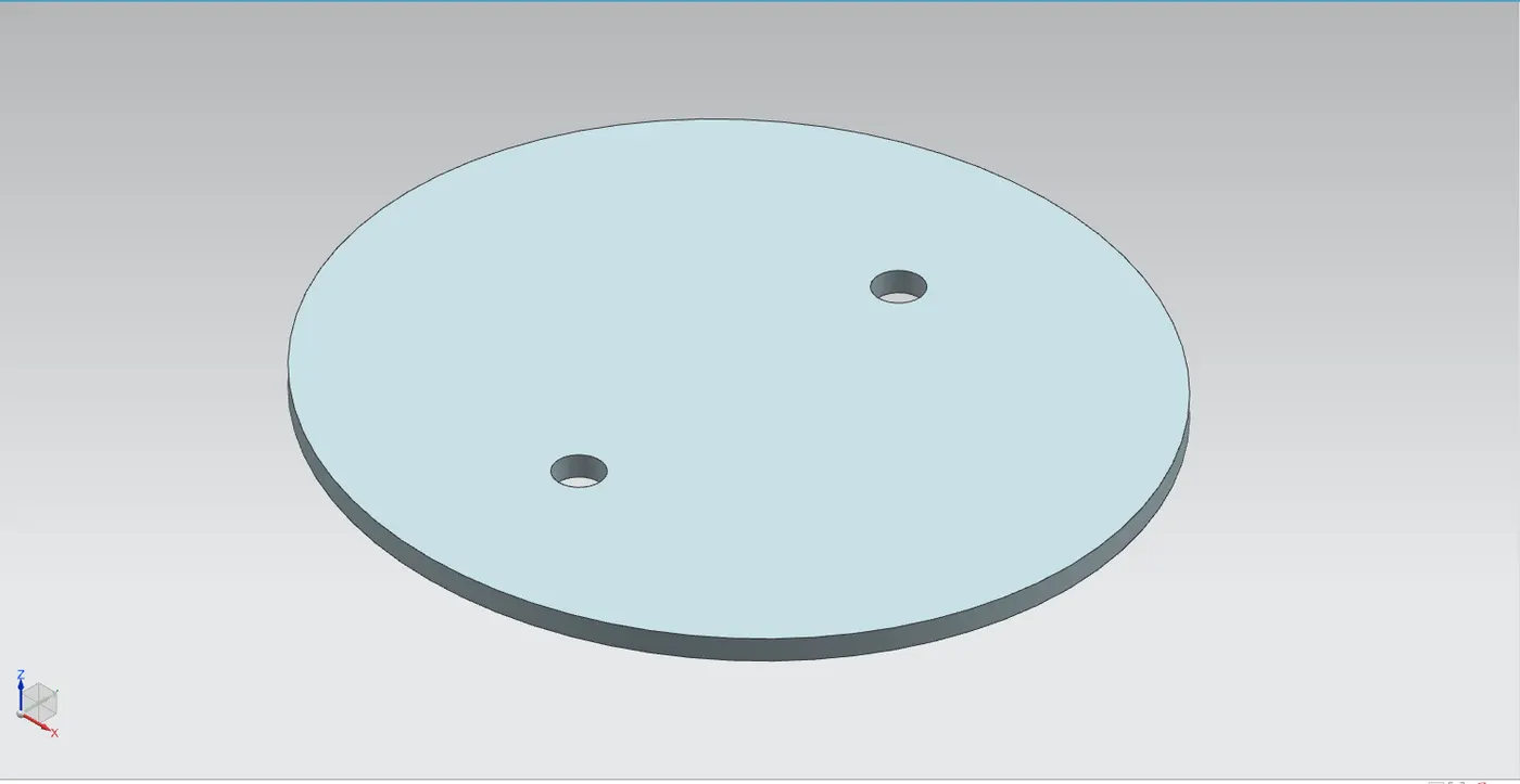
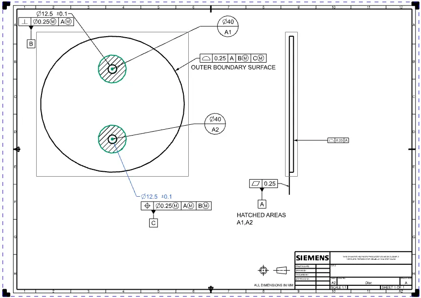
- This disc plate is the main component of the butterfly valve which regulates the flow inthe valve .The orientation of the disc determines the flow rate of the fluid .It is not perfectly circular ,rather it is elipiticalin profile .The hoels init help to position it properly on the shaft created earlier.
- A simple feature like extrude can create this part in NX .THe image of the disc plate is shown below.
GD&T applied Drawing of Disc:
Lever:
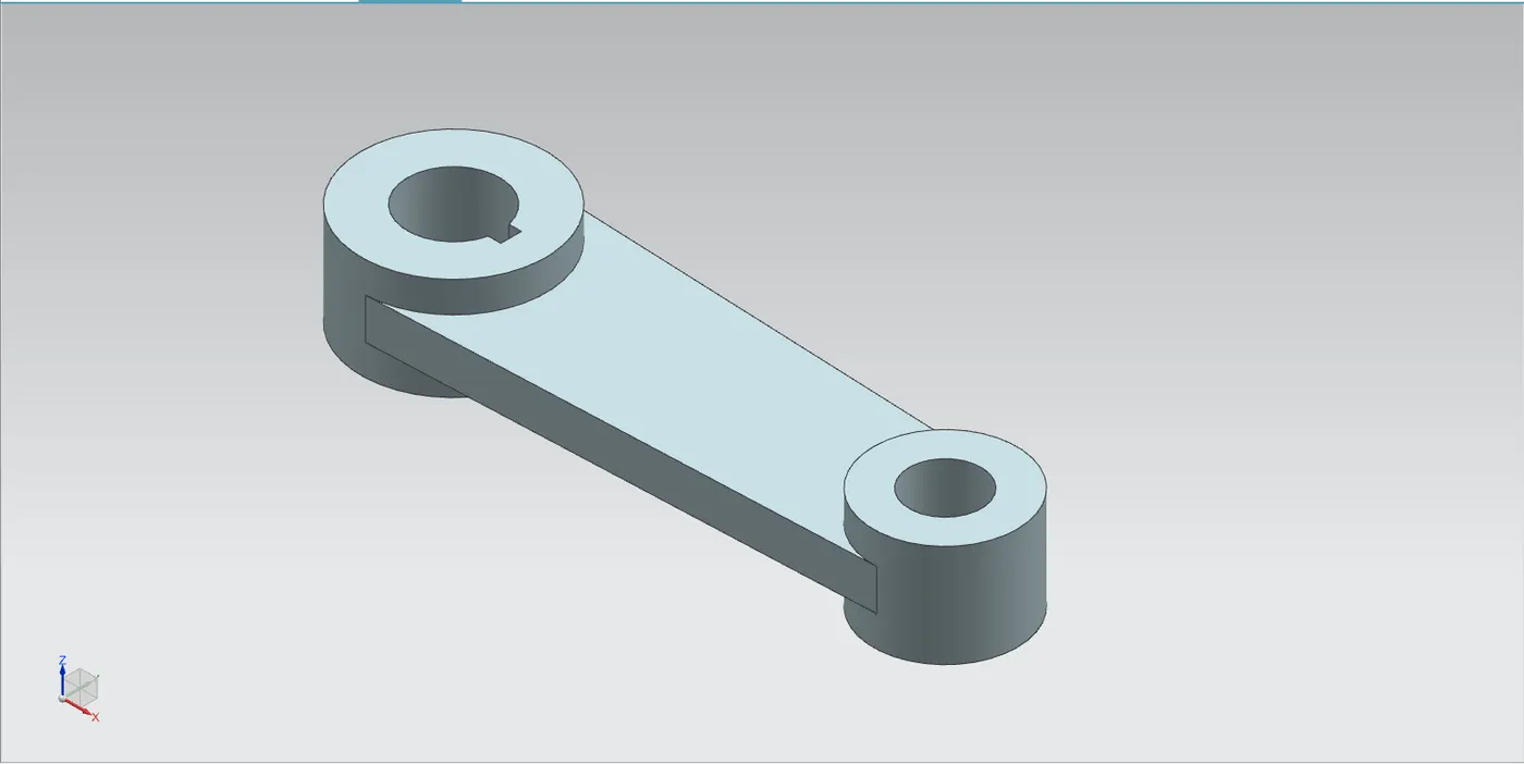
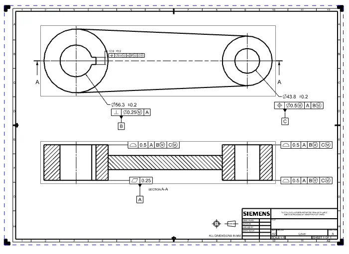
- A Lever is a handle that is used to rotate in order to regulate the flow.It is attached to the stem with the help of a key to fixing it in position with respect to it.So whenit is rotated the stem rotates which in turn rotates the disc and regulates the flow inside the pipe .It is created usingsimple features like extrude in NX after the proper base sketch is created .The image of the lever is shown below.
GD&T applied Drawing of Lever:
Nut:
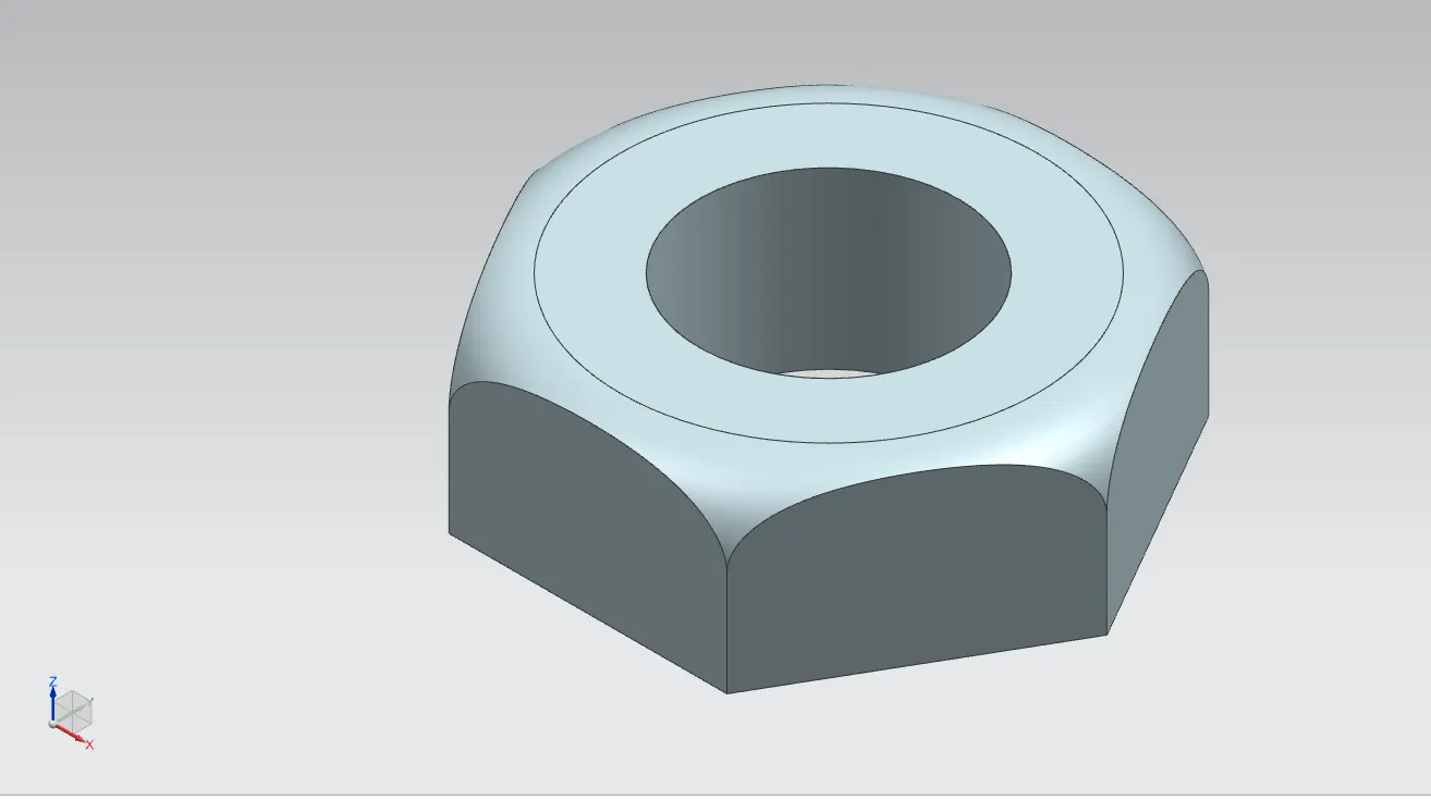
- It is the last part that helps to fix the lever in position with the stem it allows to keep it in position or to disassemble whenever required .It is created using simple extrude and revolve features in NX.
- The image of the NUT shown below.
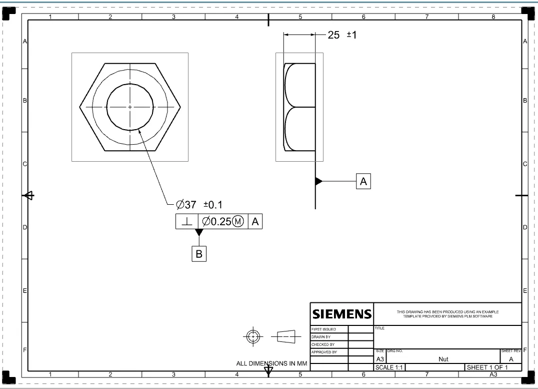
GD&T applied Drawing of Nut:
Assembly:
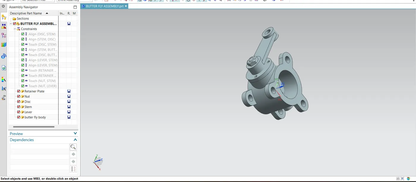
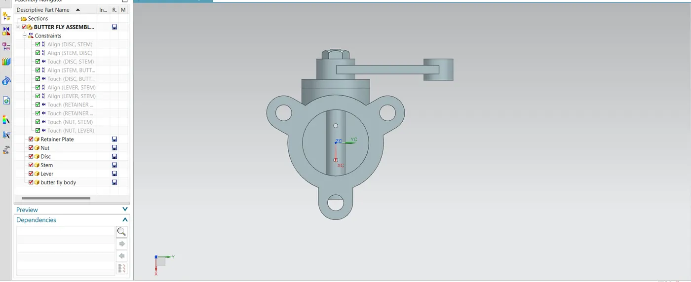
- The assembly is created by first adding all the sub parts in assemble in the assemble sheet.
- Use of assembly constraints align the axis of disc and stem holes and touch the both surfaces.
- Using moving componet to put the stem into the body and align the axis of stem and butterfly body and use touch command to surface of disc and butterfly valve body.
- lever to be align axis with the stem axis and direction of the stem and lever the key way are insame direction to join with help of command of align the side surface fo lever and other side surface of stem .
- Retainer to be align the axis with stem then touch with the butter fly body .
- Finally nut has to align the axis of stem than use touch constraint to below surface of nut and upper surface of lever .
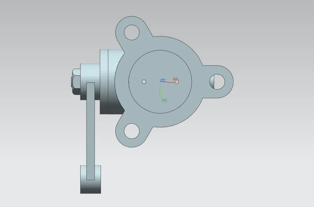
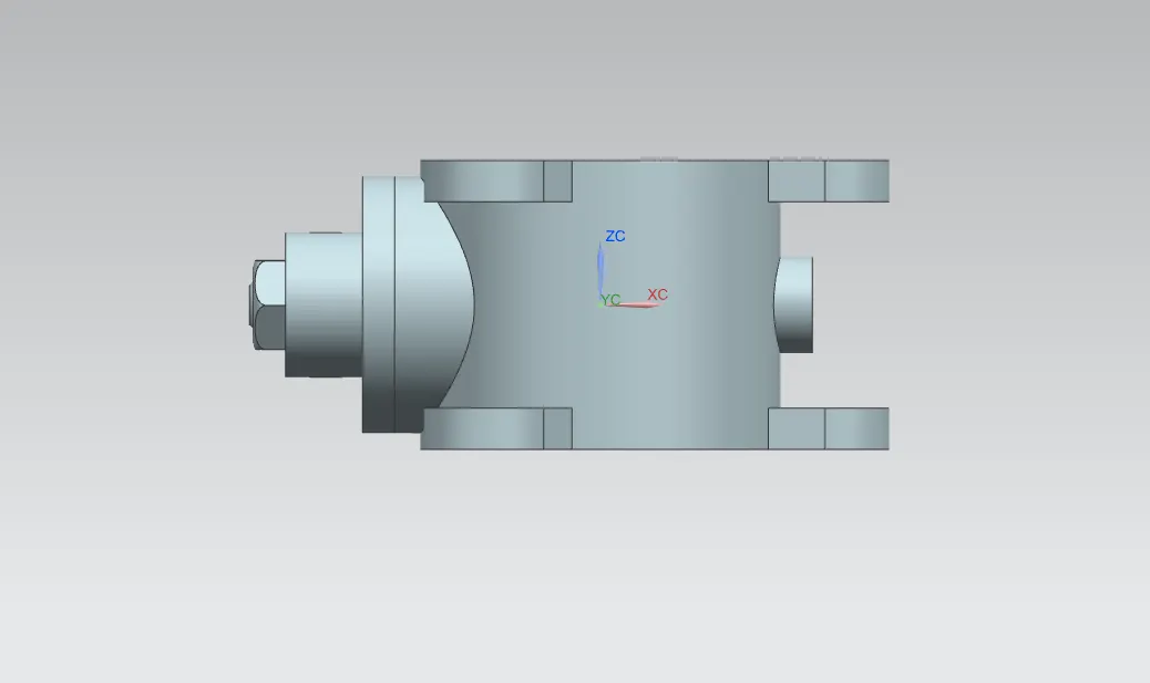
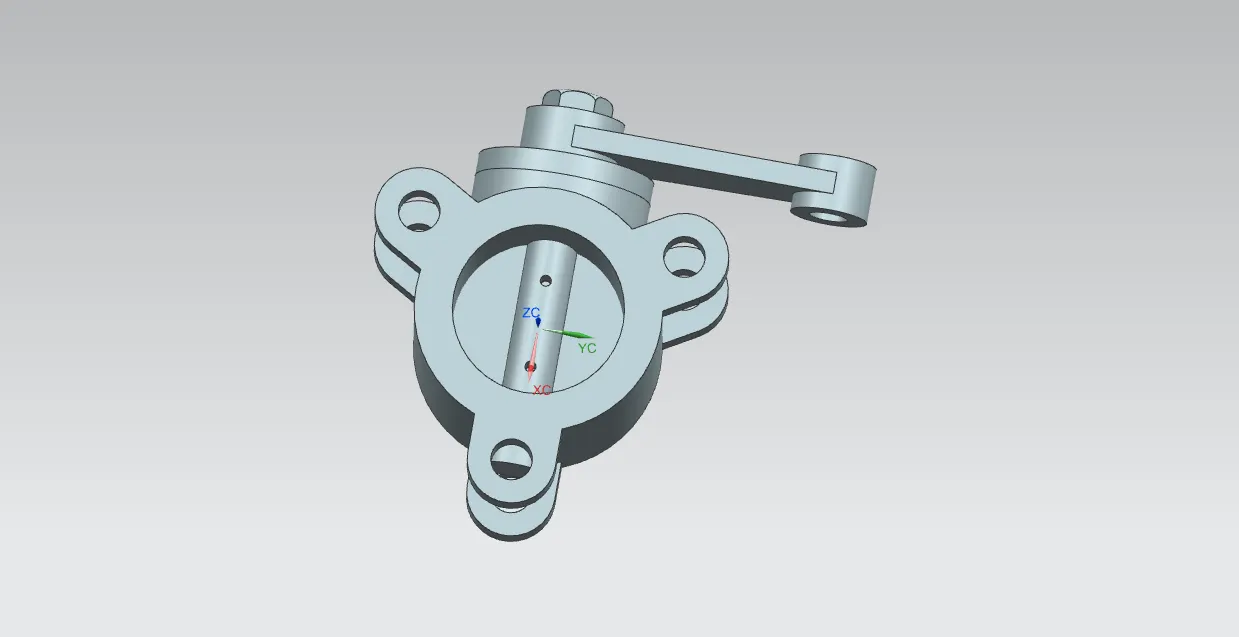
Different views of Butterfly Valve Assembly:
Drafting:
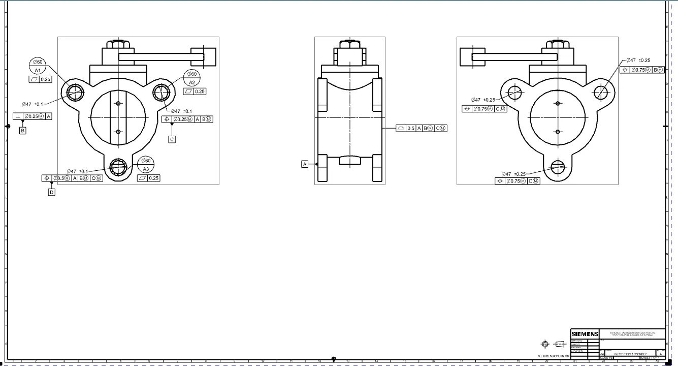
- Select the Drafting inthe application sheet is A0 and scale is 1:2
- Add the base view to the view is top view orientation is normal direction as z-axis direction and x direction as y axis.
- from this view projected the view in other direction.
- From that view opposite direction of the butter fly valve is projected on the sheet.
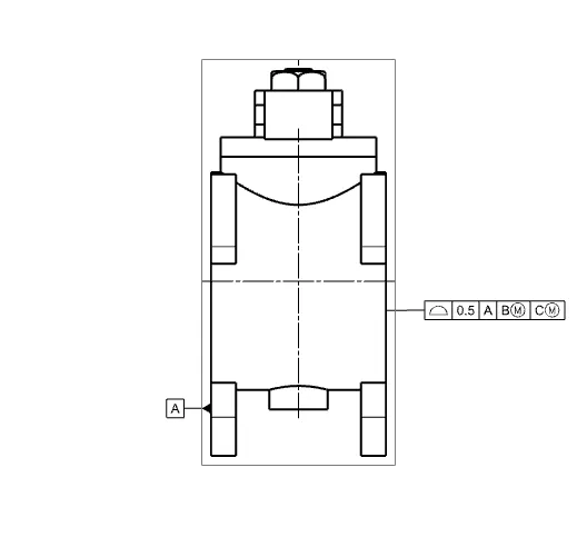
- For the projected view represent the flat surface of the left side is taken as Datum A
- For the other side of Datum A is represent as profile on surface with tolerance of0.5mm relative to Datum A DatumB with maximum material boundary Datum C with maximum material boundary.
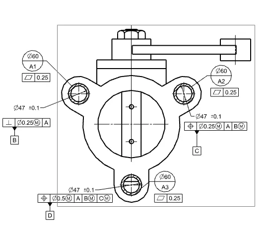
- In this sheet for the three circles are annoate as datum target area for that we have use arc /center circle to draw a circle of 30mm take a midpoint of circle for the denote the area with the hatch.
- use the hatch command to select the both circles as boundary curve and midpoint of the circle is point to establish the hatch.
- In the cross lines are to be appeared is hatch area.
- Given the datum target area circles as A1,A2,A3 with a diameter of 60mm with the feature control frame of flatness geometric characteristic with tolerance of 0.25mm.
- Left circle is the diameter of 47mm with tolerance of +- 0.1 taken as Datum B represent with feature control frame of perpendicularity geometric characteristic with the diameter 0.25mm at maximum material condition relative to datum A it is denoted as Datum B.
- Right circle is diameter of 47mm with tolerance of +- 0.1 taken as Datum C represent with feature control frame of position with respect to the diametric bonus tolerance of 0.25mm with maximum material condition relative to Datum A ,Datum B With maximum Material boundary it is denoted as Datum C .
- For the below circle of diameter opf 47mm tolerance of +-0.1mm apply a positon tolerance of diametric bonus tolerance of 0.5mm with maximum material condition realtive to Datum A , DatumB with maximum material boundary Datum C with maximum material boundary. it is denoted as Datum D.
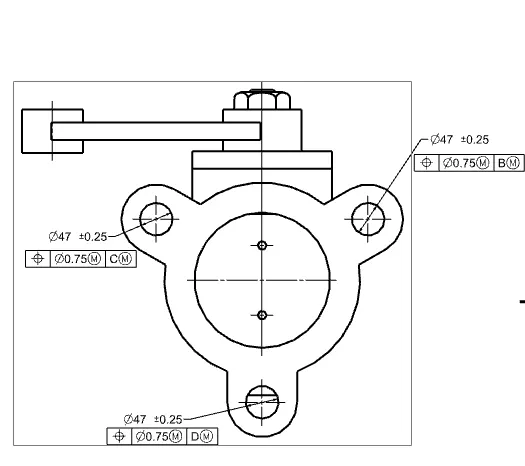
- Other side of the assembly given the feature control frames for the holes .
- Right side circle diameter of 47mm with the tolerance of +- 0.25mm to this feature control frame of positon geometric characteristic with diametric tolerance of 0.75mm with maximum material condition relative to Datum B at maximum material boundary.
- Left side circle diameter of 47mm with the tolerance of +- 0.25mm to this feature control frame of positon geometric characteristic with diametric tolerance of 0.75mm with maximum material condition relative to Datum C at maximum material boundary.
- Below circle diameter of 47mm with the tolerance of +- 0.25mm to this feature control frame of positon geometric characteristic with diametric tolerance of 0.75mm with maximum material condition relative to Datum D at maximum material boundary.
Conclusion:
The Butterfly was sucessfully designed and apply GD&T to all Parts and the assembly of the Butterfly Valve.