Week 14 challenge
OBJECTIVE:
- The objective is to design & assemble the components of the butterfly valve using various modeling & assembly features in SIEMENS NX CAD.
- Developing drawing sheets of butterfly valve assembly using various drafting tools.
- Understanding various GD&T symbols and applying the same to the butterfly valve assembly.
INTRODUCTION:
A butterfly valve belongs to a family of QUARTER-TURN valves. A butterfly valve is a flow control device that incorporates a rotational disk to control the flowing media in a process. The disk is always in the passageway, but being relatively thin, it offers little resistance to flow.
In operation, the valve is fully opened or closed when the disc is rotated a quarter turn. When the valve is closed, the disc is turned so that it completely blocks the passageway. And, when the valve is open the disc is rotated a quarter turn/90 deg so that it allows the unrestricted flow of the fluid. The valve may also be opened incrementally to throttle flow. Many different types of valves are used in flow control. They are used for a variety of reasons, such as phase (liquid or gases), pressure, piping restrictions, and solids content. Other valves are chosen for their capability to open and close in a quarter turn.
Early use of butterfly valves focused on water applications, but new designs and component materials have allowed them to be utilized in growing industrial fluid applications. Presently, butterfly valves can be found in almost every chemical plant handling a variety of diverse fluids.
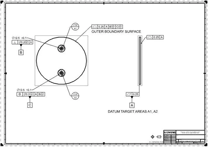
Once the components and assembly are developed, GD&t(geometric dimensioning and tolerancing) is applied to each component as well as the assembly. The purpose of GD&T is to describe the engineering intent of parts and assemblies. GD&T can more accurately define the dimensional requirements for a part, allowing over 50% more tolerance zone than coordinate (or linear) dimensioning in some cases. Proper application of GD&T will ensure that the part defined on the drawing has the desired form, fit (within limits), and function with the largest possible tolerances. GD&T can add quality and reduce cost at the same time through producibility.
There are several standards available worldwide that describe the symbols and define the rules used in GD&T. One such standard is the American Society of Mechanical Engineers (ASME) Y14.5. This article is based on that standard, but other standards, such as those from the International Organization for Standardization (ISO), may vary slightly. The Y14.5 standard has the advantage of providing a fairly complete set of standards for GD&T in one document. The ISO standards, in comparison, typically only address a single topic at a time.
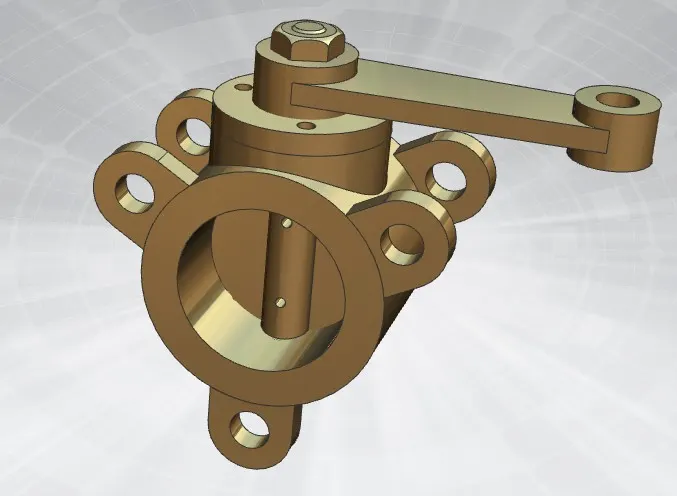
COMPONENTS OF BUTTERFLY VALVE:
Various components of the butterfly valve have been designed, and GD&T is applied to the drawing sheets. The following details are given below:
1. BODY OF BUTTERFLY VALVE
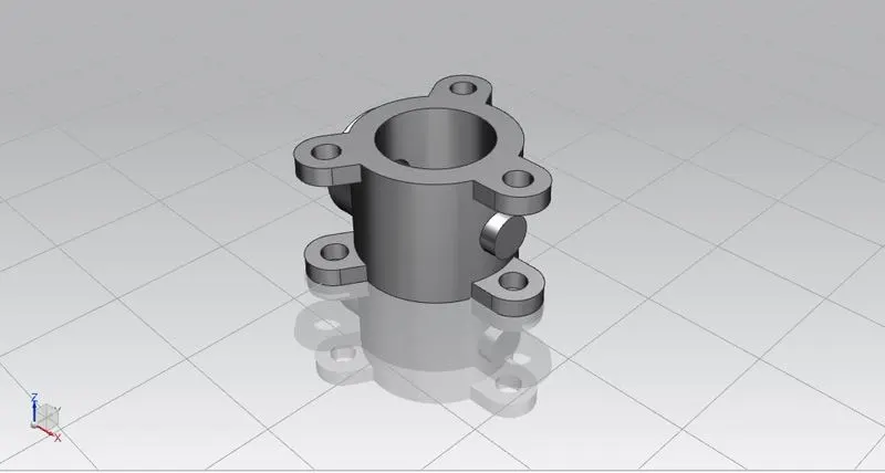
- Butterfly valves generally have bodies that fit between two pipe flanges. This butterfly valve has a lug body design consisting of protruding lugs that provide bolt holes matching those in the pipe flange.
- Create two circles of required diameter and use Extrude command to form a cylindrical body/housing.
- On that cylindrical body create three lugs with holes in them. This will help us connect the butterfly valve to the pipe flanges. We have created the lugs on the mid-plane and then Extruded them with reference to the mid-plane(i.e. symmetrical value).
- Using the Move object command we created similar lugs on the outer surfaces of the body with the help of lugs created earlier.
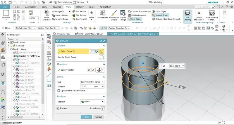
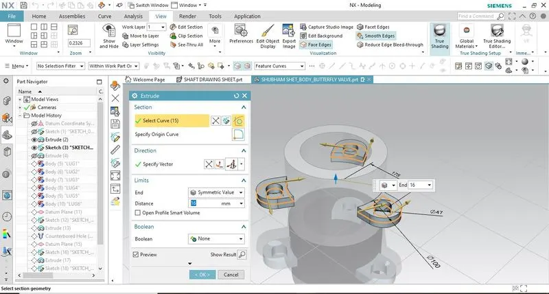
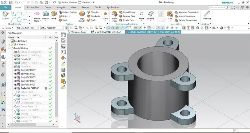
- Create a new datum plane and draw a circular sketch of the required diameter. Extrude this sketch up to the cylindrical body using extrude command.
- Then create counterbored holes in the body using the Hole command so that we can insert shaft/stem in it. Specify all the required values of diameter and hole depth accordingly.
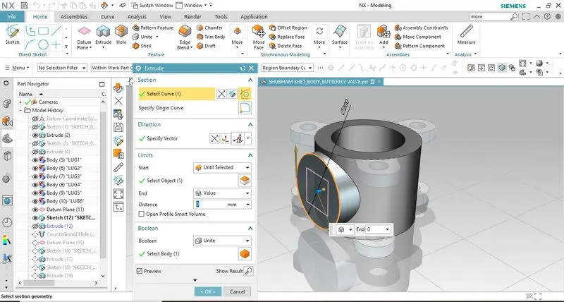
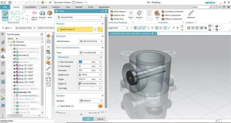
Create another datum plane on the other side of this newly created feature. Develop a circular sketch on this new plane and then extrude it up to the cylindrical body.
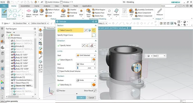
On the outer surface of the parent feature of the counterbored hole, create three small holes using extrude command so that we can assemble other components to the body
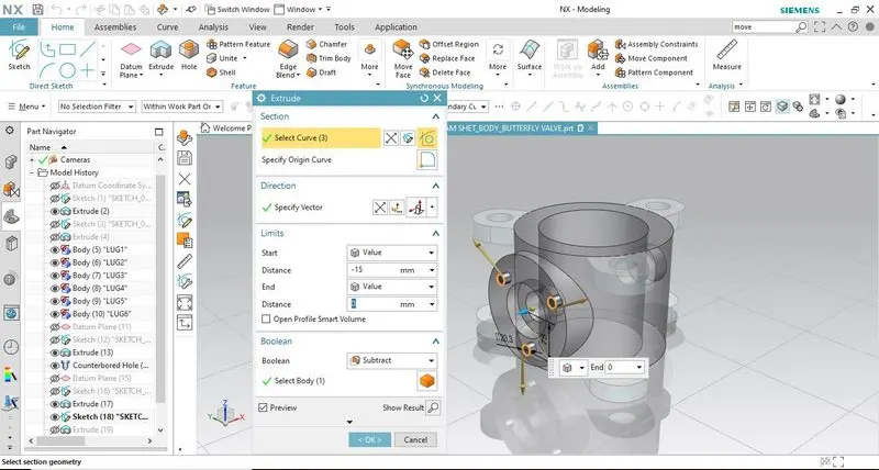
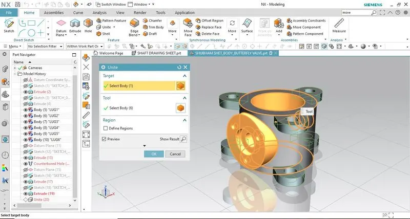
Combine all the features to form a single object using Unite command.
Model Views:
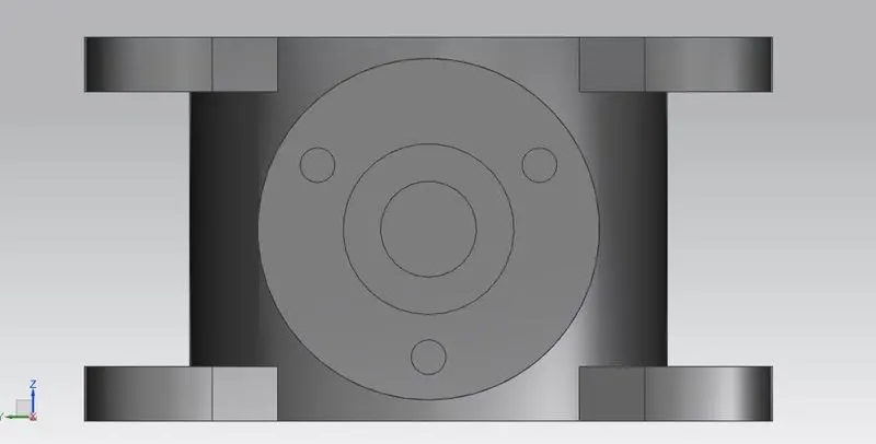
Front View
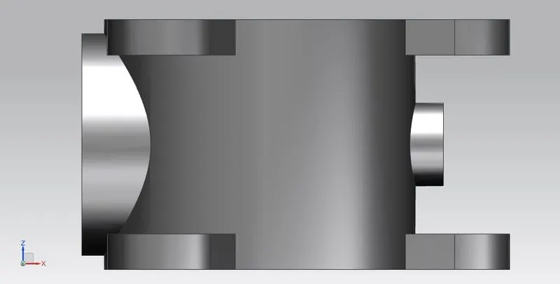
Side View
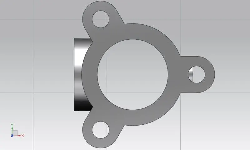
Top View
Isometric View
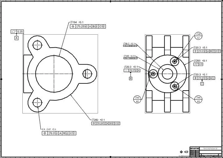
DRAWING SHEET WITH GD&T
2. SHAFT/STEM OF BUTTERFLY VALVE
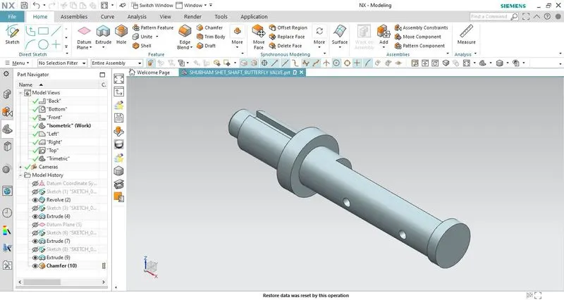
The stem of the butterfly valve may be a one-piece shaft or a two-piece (split-stem) design. This design consists of a one-piece shaft. The disc/plate, lever, and nut are assembled to this shaft.
First, create a sketch that is cylindrical in shape along with steps. That sketch must be fully constrained and closed in order to use Revolve command.
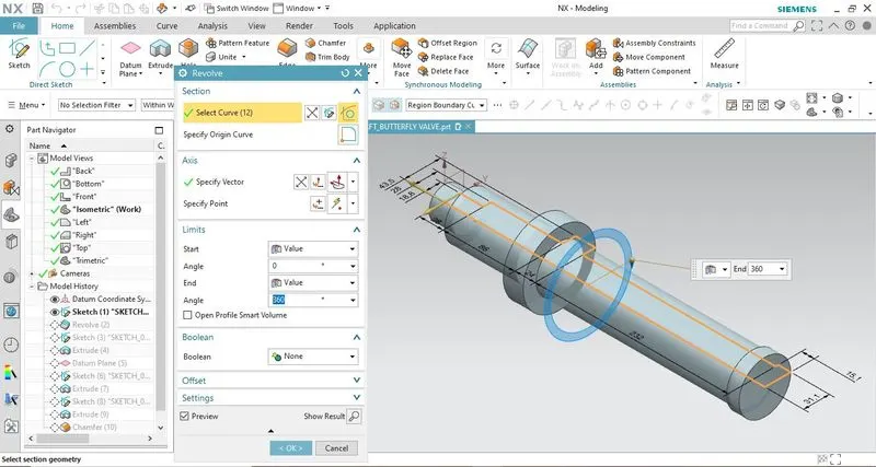
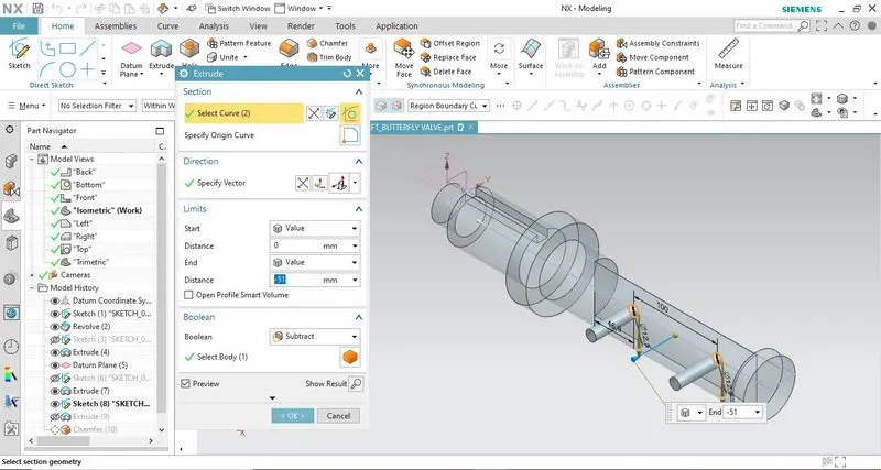
After creating the main body we have to create two rectangular slots on it.
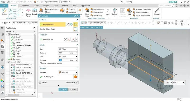
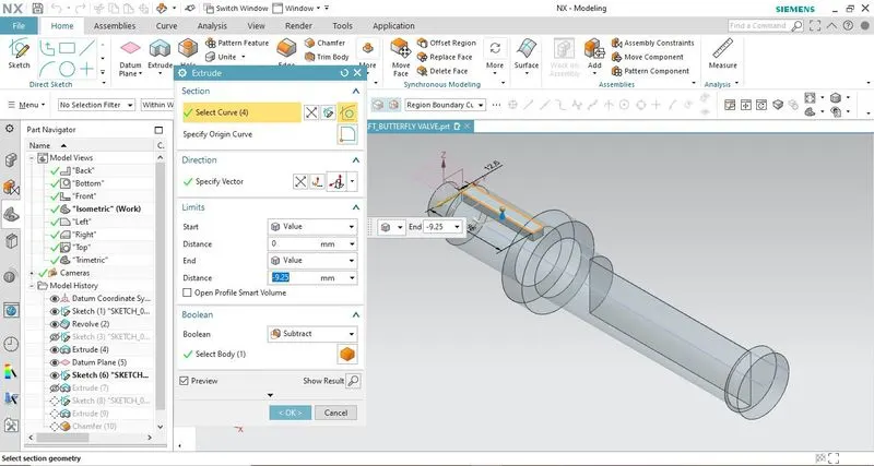
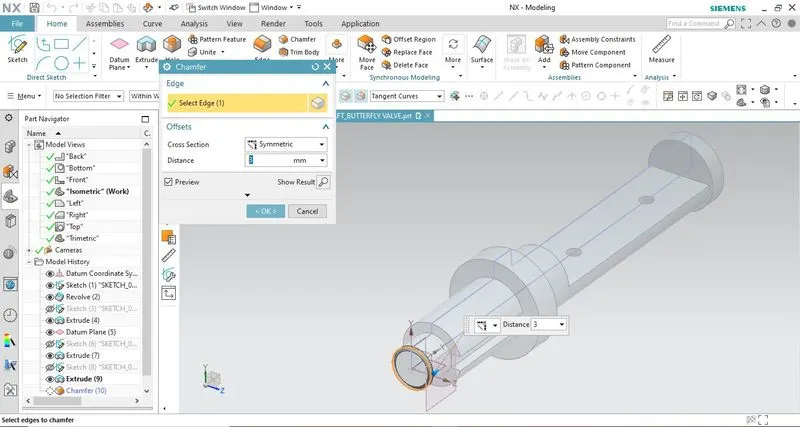
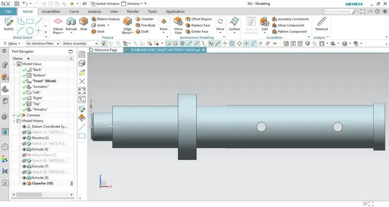
Then create two holes on the face of the bigger slot where the disc/plate will be attached. Then provide a chamfer on the front circular edge for better handling and safety reasons.
Model Views:
Front View
Side View
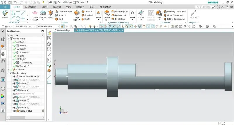
Top View
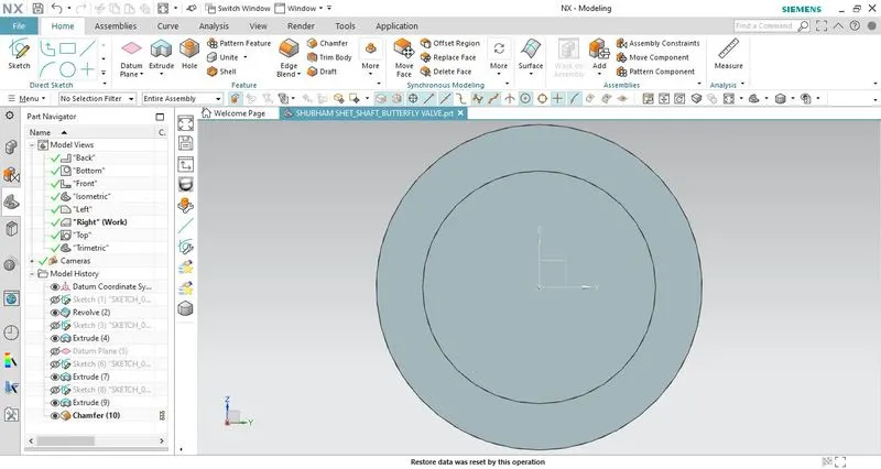
Isometric View
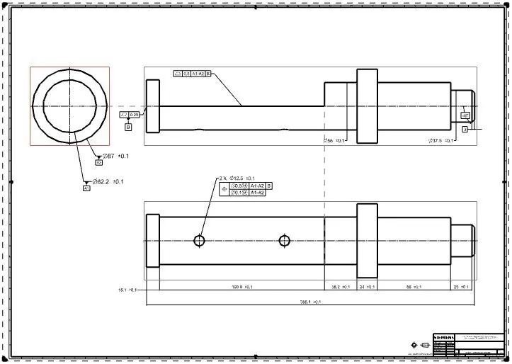
DRAWING SHEET WITH GD&T
3. RETAINER OF BUTTERFLY VALVE
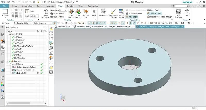
- It is nothing but a kind of washer assembled on the body of the butterfly valve.
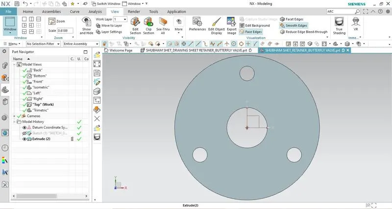
- Create a circular sketch with an appropriate diameter. Also, create 3 holes in the sketch that will help us to fix the retainer to the body of the butterfly valve.
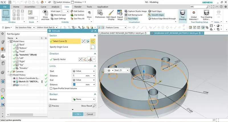
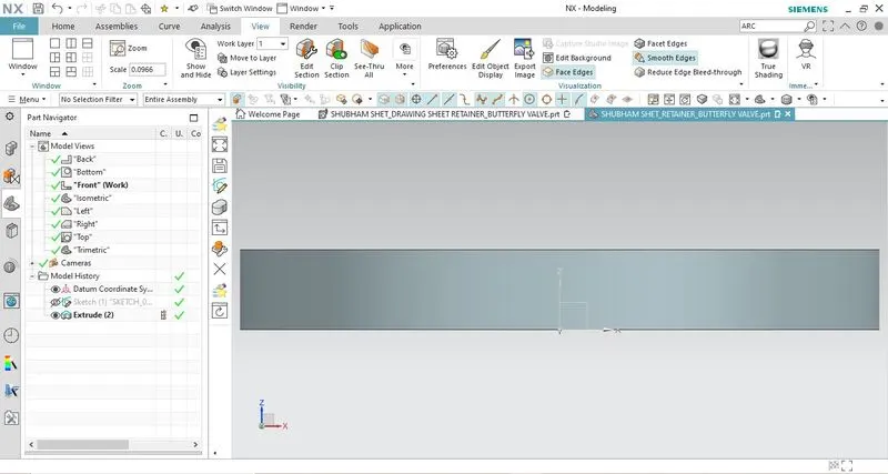
Model Views:
Front View
Top View
Isometric View
DRAWING SHEET WITH GD&T
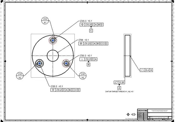
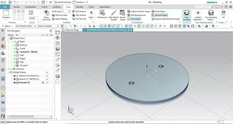
4. DISC PLATE OF BUTTERFLY VALVE
A disc is nothing but a flow controlling/closure member of the butterfly valve which is attached to the stem/shaft. The disk is the equivalent of a plug in a plug valve, a gate in a gate valve, or a ball in a ball valve.
Rotating the disk one-quarter turn or 90 Degrees opens and closes the butterfly valve.
Create an elliptical sketch with appropriate sizes (major & minor distance). Then put two holes along the minor axis which will be used to fix the disc to the shaft.
Extrude the fully constrained sketch by providing suitable thickness.
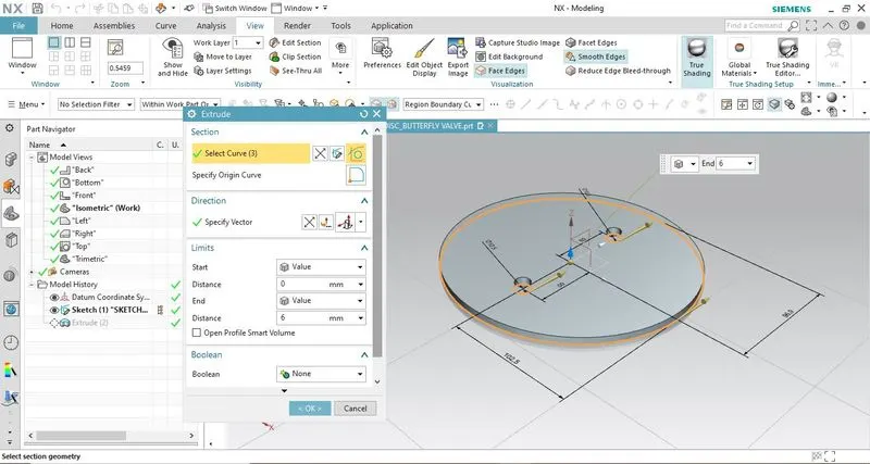
Model Views:
Front View
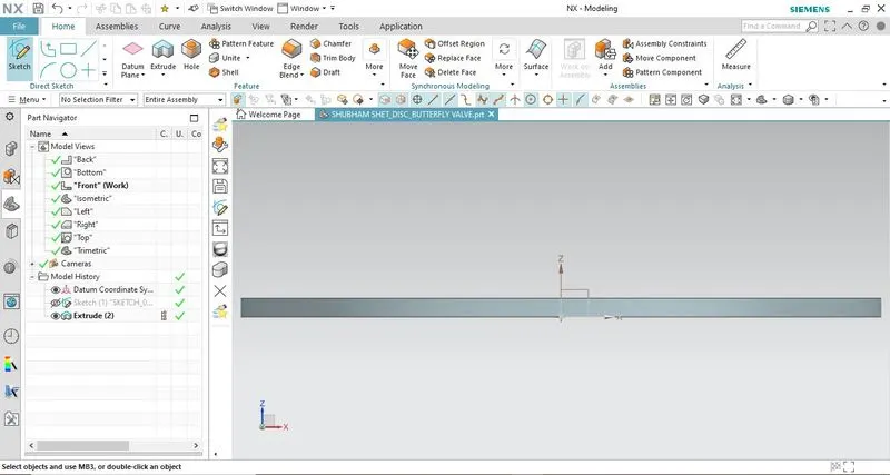
Top View
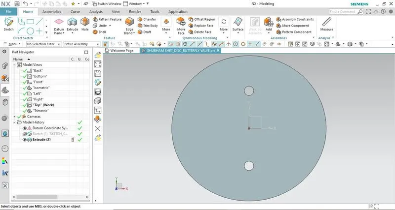
Isometric View
DRAWING SHEET WITH GD&T
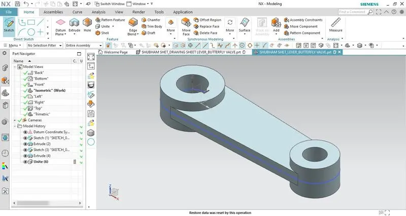
5. LEVER HANDLE OF BUTTERFLY VALVE
The lever is attached at the end of the shaft/stem above the body & retainer. This lever handle is used in a small-sized butterfly valve. Using this we can regulate the flow by opening and closing the disc whenever required.
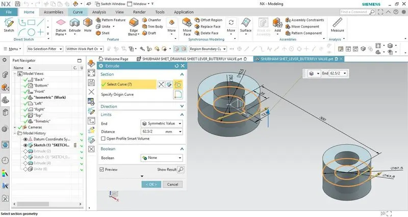
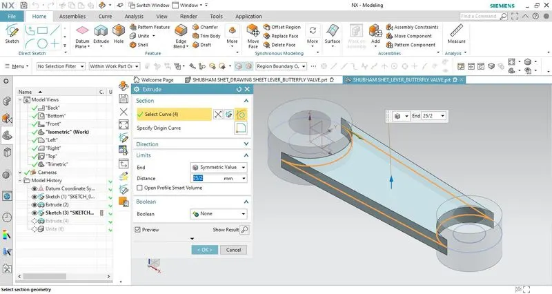
Create two circular sketches with the appropriate diameters, and specify a suitable distance between them. Also, create a keyway slot in the bigger diameter sketch. Join these two sketches with a line tangent to both the circles.
After creating the fully constrained sketch, first, extrude the circular regions and then extrude the mid-section with different thickness values.
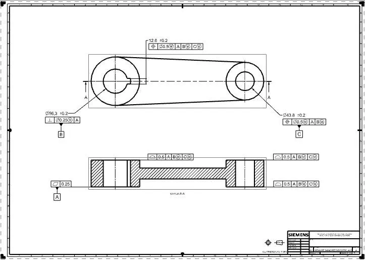
Then combine all the features using Unite command. Then create a drawing sheet of the model and apply GD&T to the drawing.
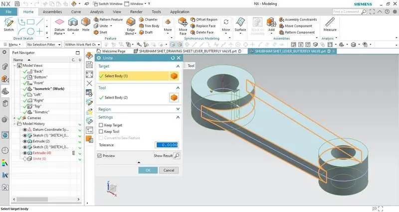
Model Views:
Front View
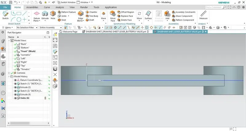
Side View
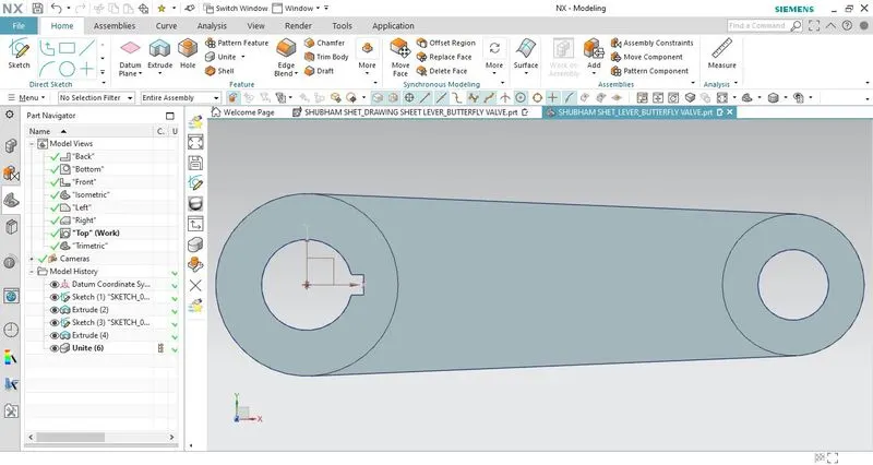
Top View
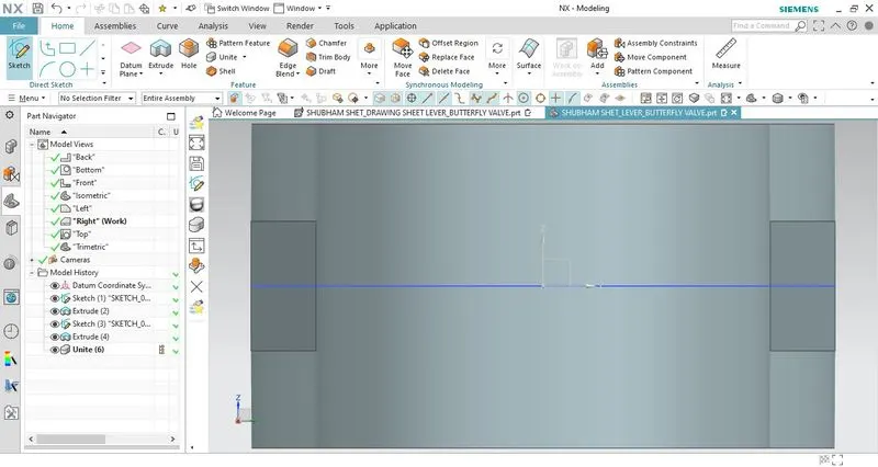
Isometric View
DRAWING SHEET WITH GD&T
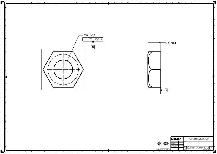
6. NUT-BUTTERFLY VALVE
It is used to keep the lever and retainer intact with each other as well as the body of the butterfly valve.
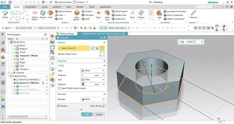
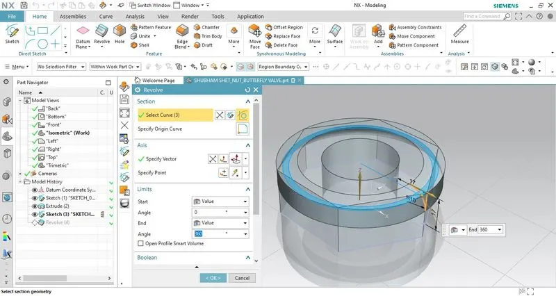
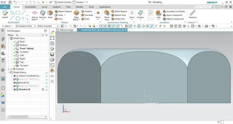
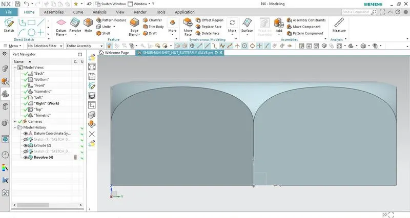
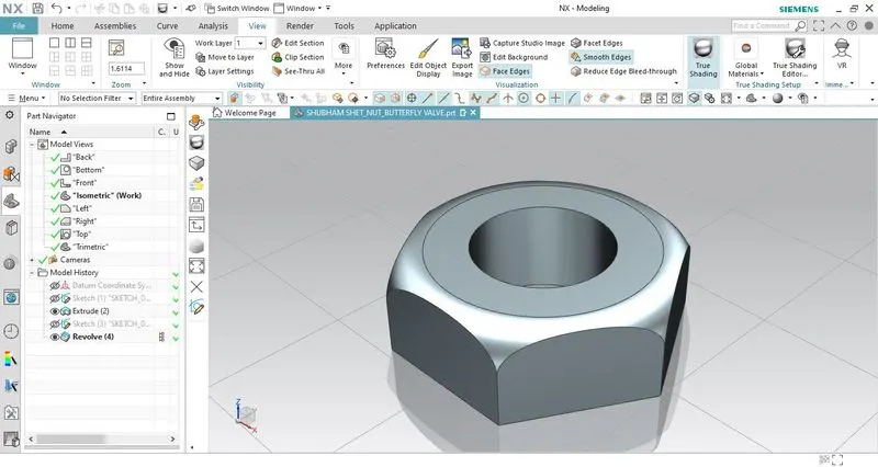
Create a polygon sketch (6sides) with suitable dimensions. Also, add a circular hole in the sketch so that it can be inserted into the shaft.
For safety handling provide a fillet on the top edge of the nut.
Model Views:
Front View
Side View
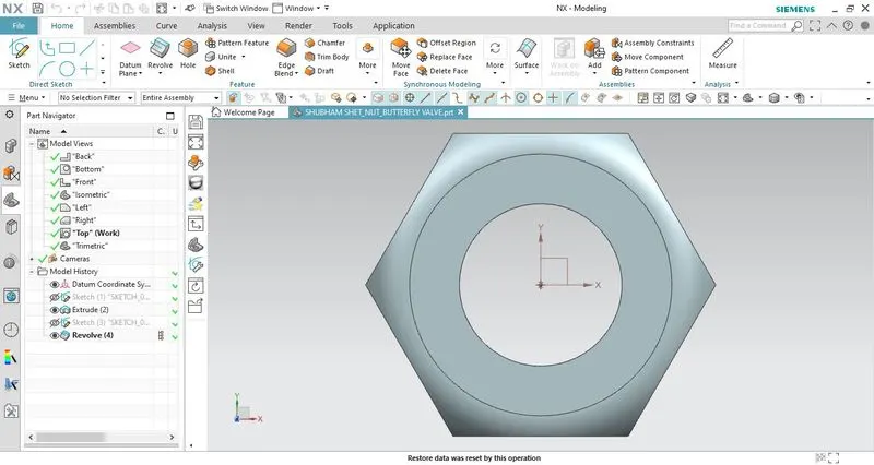
Top View
Isometric View
DRAWING SHEET WITH GD&T
BUTTERFLY VALVE ASSEMBLY:
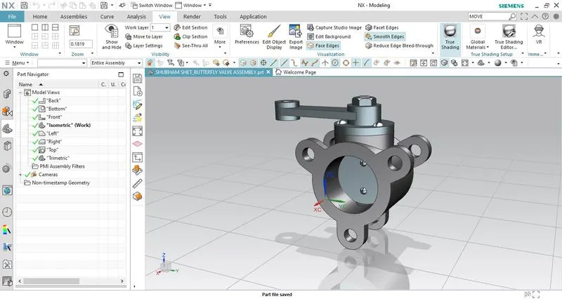
After designing every component. we have created the final assembly model using SIEMENS NX CAD.
MODEL VIEWS:
FRONT VIEW
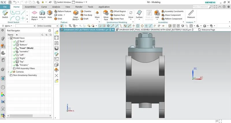
SIDE VIEW
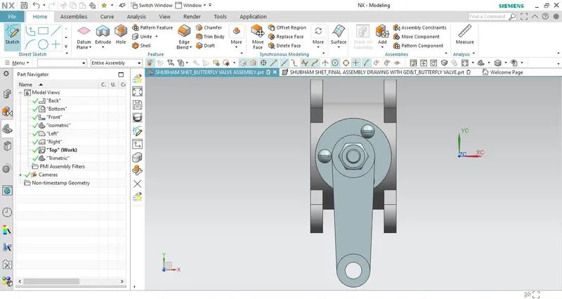
TOP VIEW
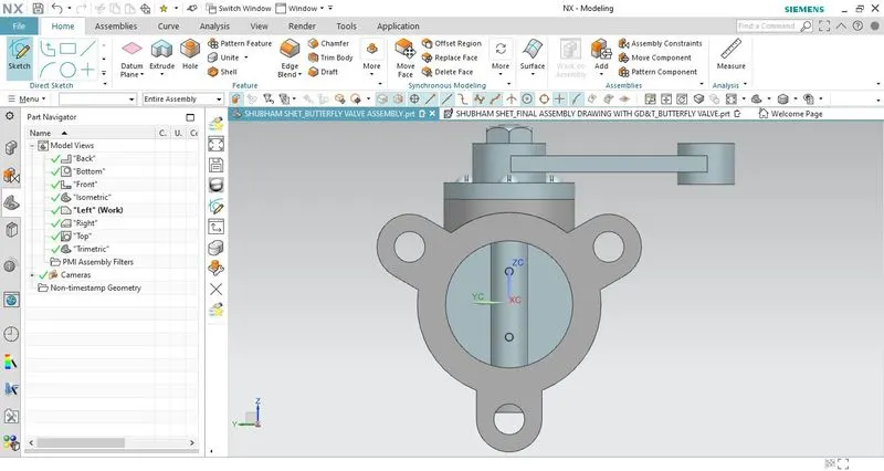
ISOMETRIC VIEW
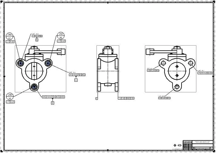
DRAWING SHEET WITH GD&T
CONCLUSION:
- Learned the significance of GD&T that states how it controls the dimensional variation in parts which leads to less wastage of material, reduces cost, and eliminates inspection of some features, being a language that consists of symbols make it easy for the engineers to communicate with other engineers all over the world.
- Also, learned how to perform stack/gap analysis using different of stack-up analysis such as RSS, MRSS, and, WC.
- Learned modeling, assembly, drafting applications in SIEMENS NX CAD and developed a butterfly valve. Also, applied GD&T to individual components as well as the assembly of the butterfly valve.