Week 14 challenge
Aim: Assembly of all the component of Butterfly valve and apply GD& T to the assembly drawing
Software Used: NX 11
Component of Butterfly Valve:
- Body
- Shaft
- Retainer
- Disc
- Lever
- Nut
- Screws
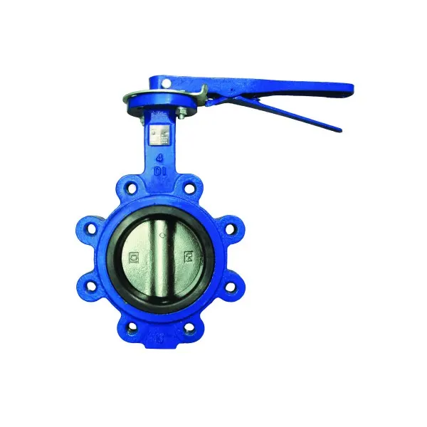
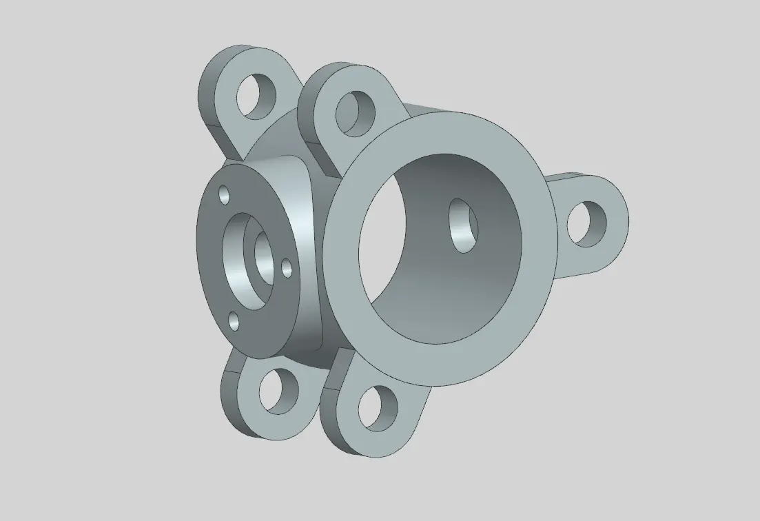
1. Body-
- In the first the sketch for the body of the butterfly valve is drawn using the tools in NX software.
- After extruding the sketch which is drawn,the ears of the Butterfly valve is drawn and then it is copied on both sides of the cyclindrical portion.
- Now, the datum plane option is used to create cyclidrical portion and the counter bore option is used to provide a counter bore to the part with the specified dimensions.
- Finally, the hole is provided for the mounting of the body and it is saved in the required folder.
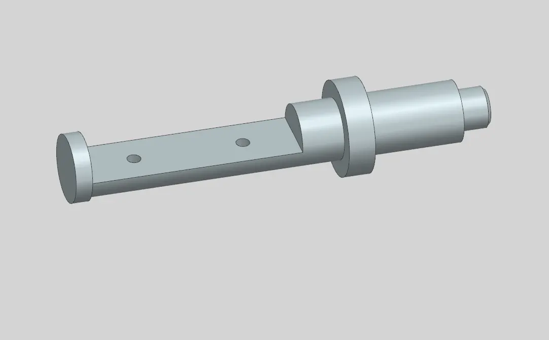
2. Shaft-
- The 2D drawing given in the figure is used to convert the Sketch into 3D model with different operations.
- The revolve option is used to create the shaft by rotating it through 360°.
- Now the extrude option(Subtract) is used to provide the recess in the front and rear portion of the shaft.
- Finally, the two holes of 12.5mm diameter is provided in the rear recess portion of the shaft and the part is saved in the required folder.
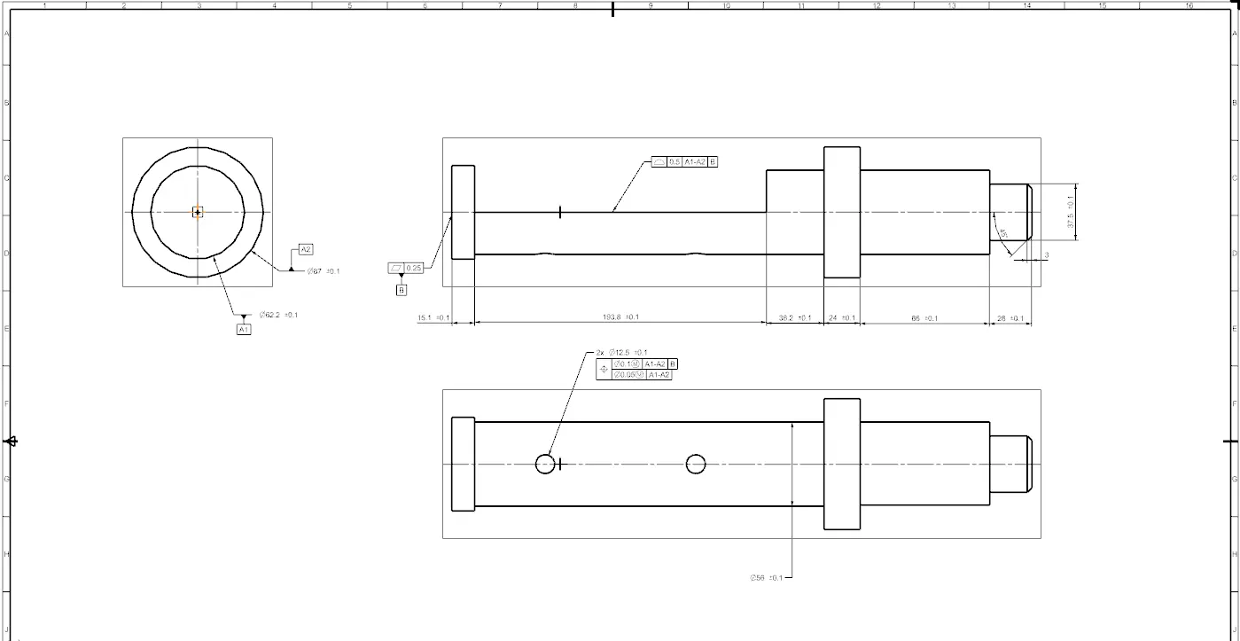
Drawing of Shaft-
- First step in applying GD & T is Constraining 6 DOF
- Here,Only two datums A and B are to constrain 5 DOF, 1 DOF is free for the movement of shaft in one direction is required as per it's function.
- Datum A1 and A2 are given which comes in contact with the body of the butterfly valve.
- Datum B is provided at the base of the shaft.
- All the other tolerances like profile of a surface,flatness, composition position tolerance and the size tolerances are given to the other features.
3. Retainer-
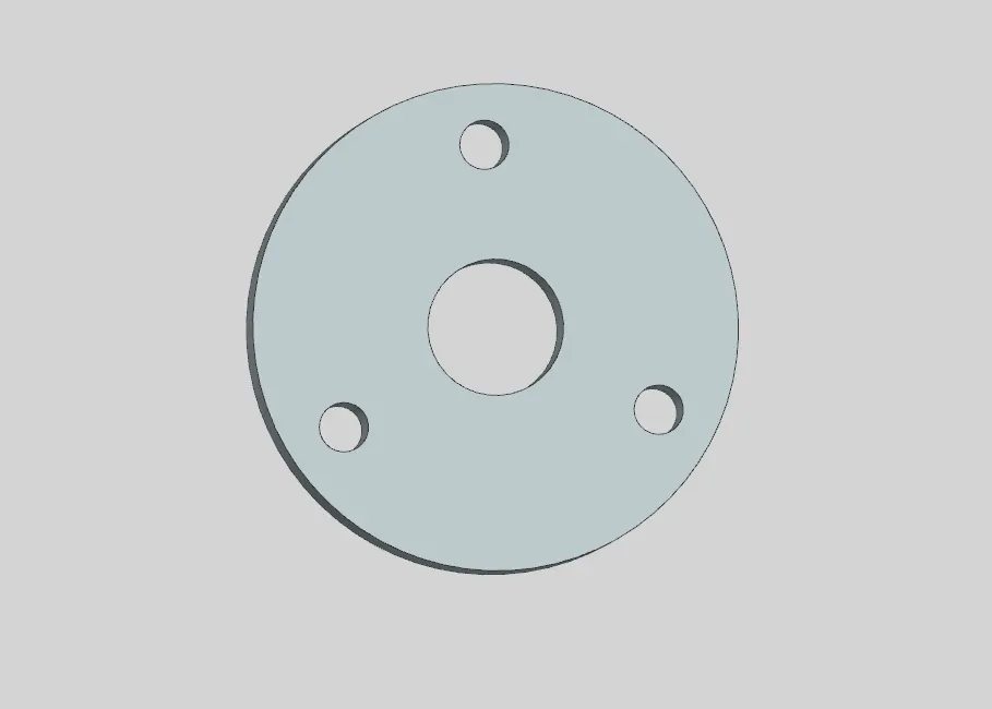
- 3D model of Retainer is created with the help of input 2D drawings
- Initially,the concentric holes of 200mm and 56mm diameter are drawn and the other 3 circles of 20.3 mm diameter is drawn with the help of 150mm BCD by using Pattern option.
- Finally, the 2D sketch is extruded and the part is saved in the required folder.
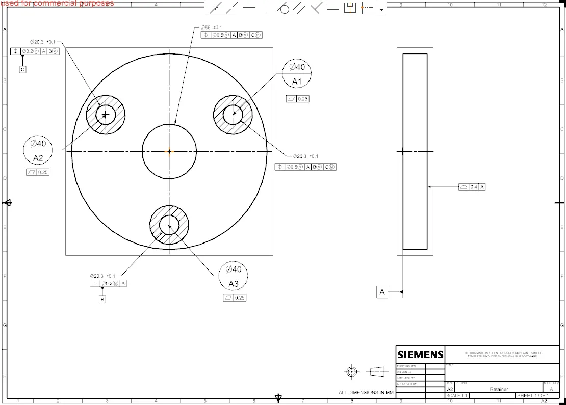
Drawing of Retainer-
- First step is to constraining 6 DOF of the part, applying GD & T to datums A,B,C and then to other functional elements of drawing.
- Datum target areas A1,A2,A3(Primary datum-A) is applied to one side of the Retainer which comes in contact with the upper portion of the body.
- Datum-B is applied to one of the holes of the retainer where the bolt is inserted.
- Datum-C is applied to the other hole of the retainer.
- Finally, the other tolerances like Perpendicularity,position,profile of a surface are applied to the other holes and the surfceof the retainer, the drawing is saved in the required folder.
4. Disc/Plate-
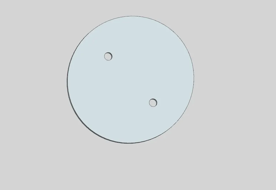
- Initailly,with the help of 2D drawing the disc plateSketch is prepared
- In which, the ellipse with a minor and major radius is created and then the two holes of 12.5 diameter is given.
- Finally, the sketch is extruded and the part is saved in the required folder.
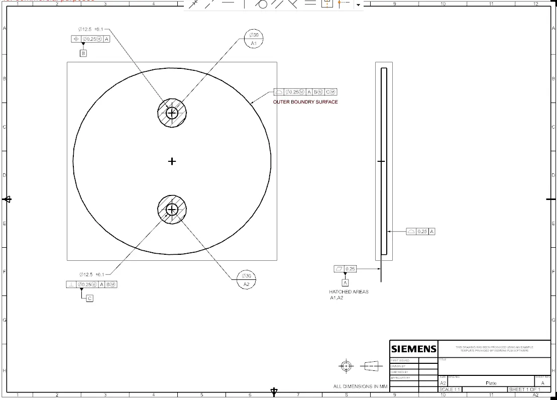
Drawing of Disc/Plate-
- The datums are applied to the disc in the drafting section in order to constrain 6 DOF
- Datum target Areas A1,A2(Primary Datum-A) is given to one side of the disc which comes in contact with the Surface of Stem/Shaft.
- A datum B (Secondary Datum)is given to one hole of the disc and the other datum is given to the other hole.
- All the other tolerances like Perpendicularity tolerance to datum B and position tolerance to datum C(Tartiory Datum) and profile of a surface tolerance is given to the outer boundary surface.
5. Lever-
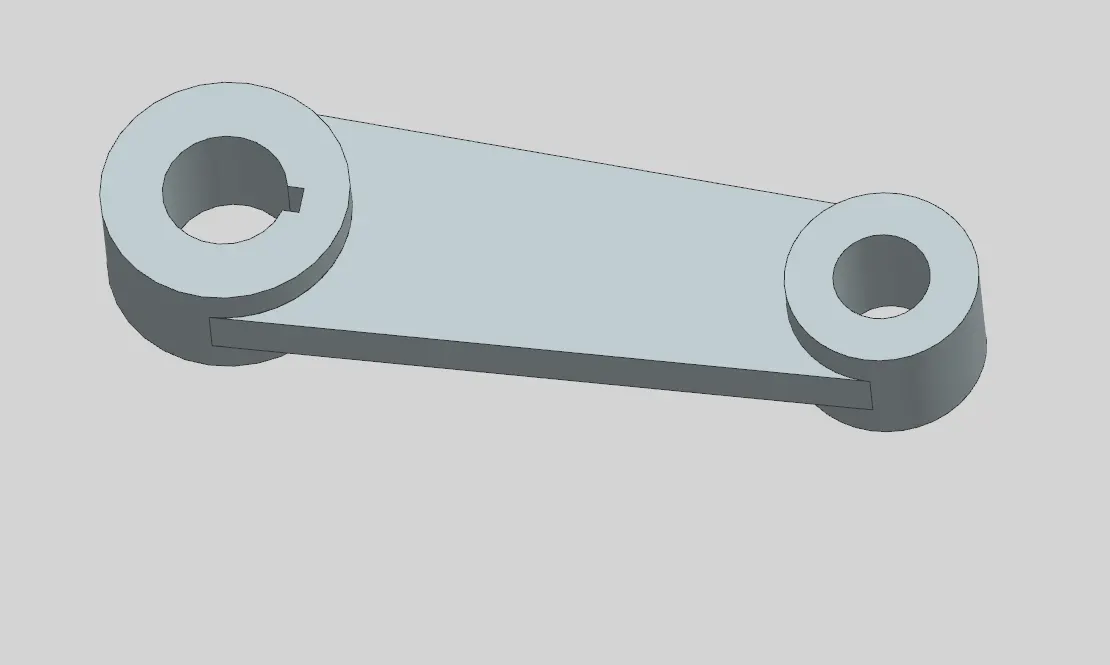
- In the first step 2d sketches are made one by one from the given inputs of 2d drawings
- And using extrude cammand the features are extruded to a certain lengths one by one
- at the same time they are attached with themselves with boolean option.
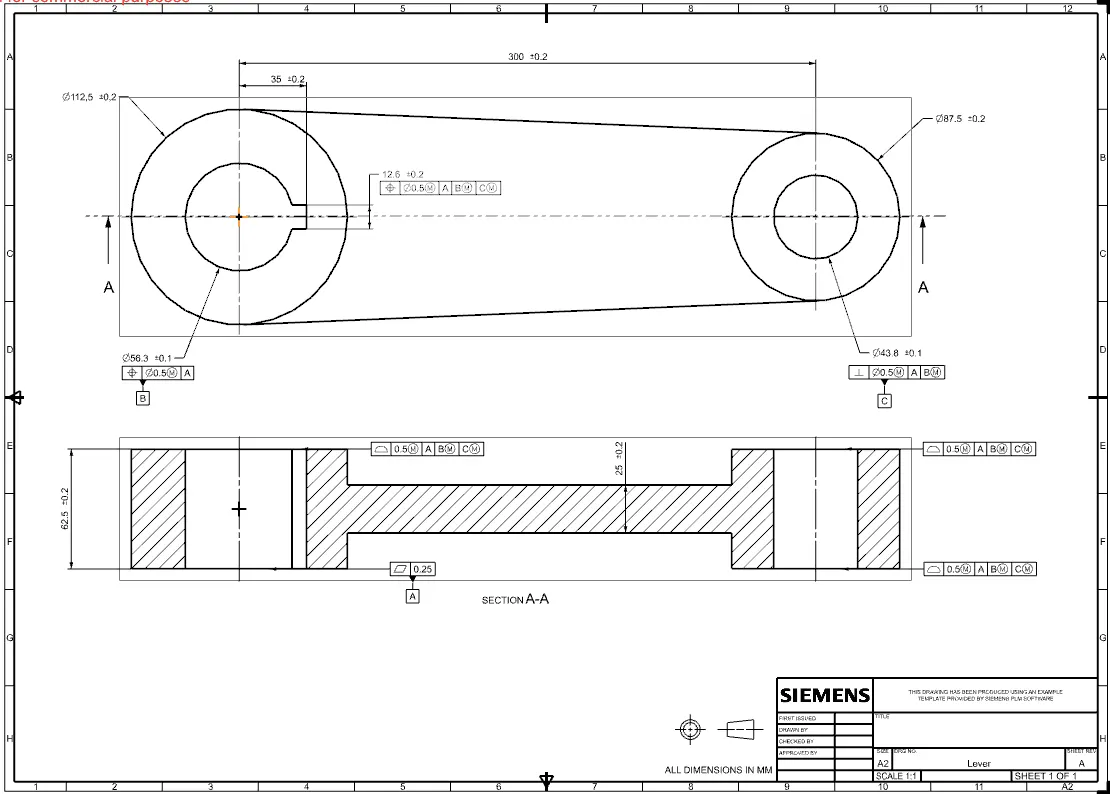
Drawing of Lever-
- After the design of the lever, the drafting of the lever is done for applying the GD&T.
- Three datums A, B, C are applied to the part.
- A datum- To the bottom surface of the lever that comes in contact with the other surface.
- B datum- It is applied to the hole where the bolt comes in contact.
- C datum- It is applied to the other hole to completely constraint the part.
- Finally, all the other tolerances like position, Flatness, Profile of a surface are applied to the part.
6. NUT-
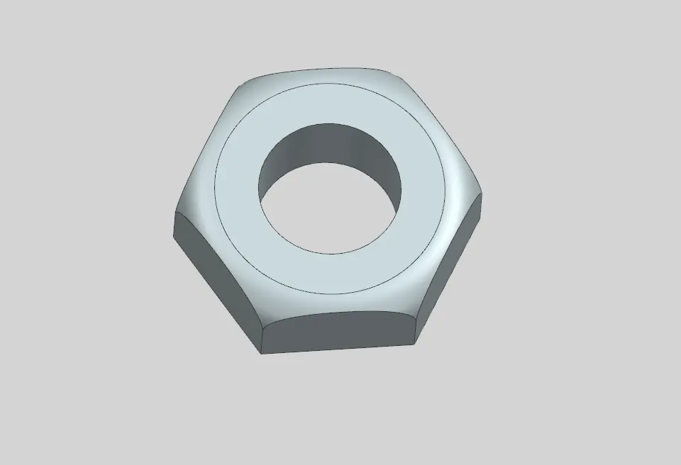
- The 3D modeling of the Nut is created with the given dimensions.
- Initially the hexagonal shaped nut is extruded with a depth of 25mm and a hole of 37mm diameter.
- Finally, the fillet of radius 10mm is provided by using the revolve option.
Drawing of Nut-
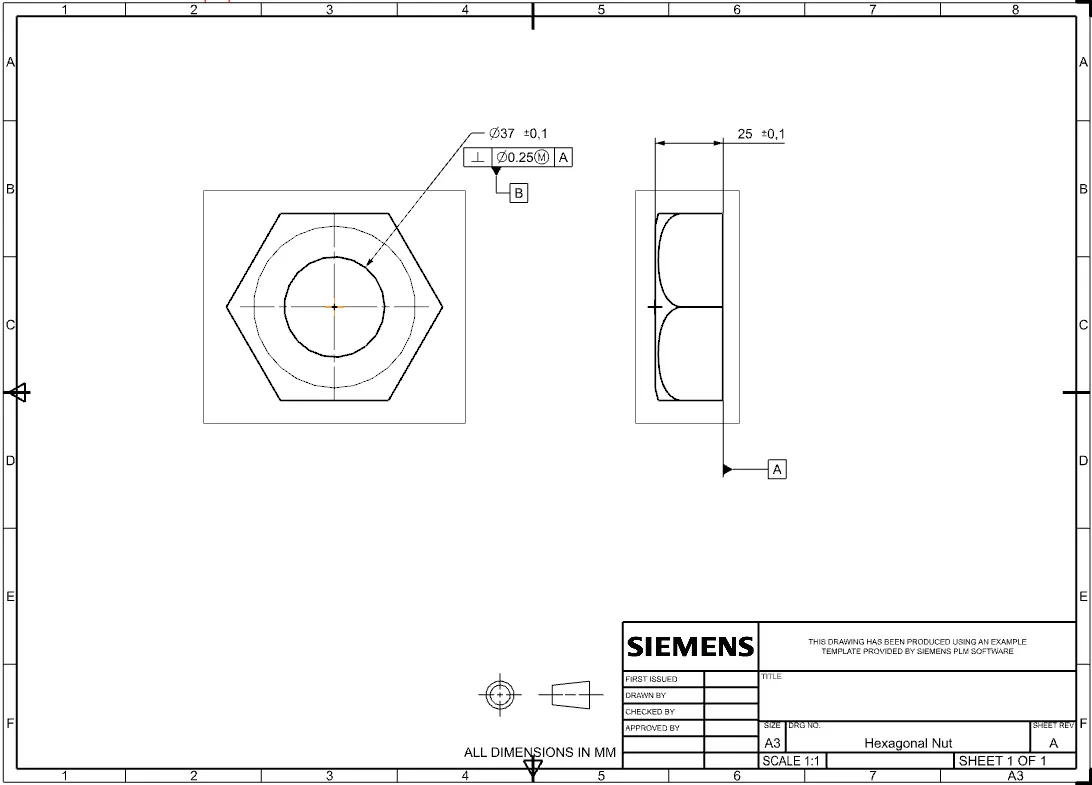
- After finished creating the design of nut,the drafting portion is opened for applying GD & T to the nut.
- Now,the datums A and B are applied to the base of the nut and the hole of the nut. Perpendicularity Tolerance of 0.25 is given to the hole of the nut.
7. Screw-
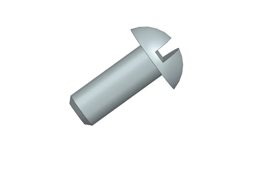
- This Screw helps to retain or to fix the Disc with the Shaft of the butterfly valve. It prevents the shaft from coming out of the body and keeps it in position for the proper functioning of the disc inside the body.
8. Assembly of Butterfly Valve-
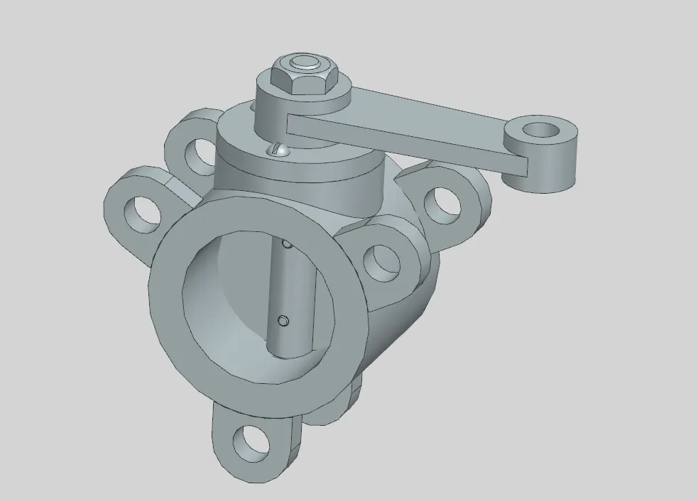
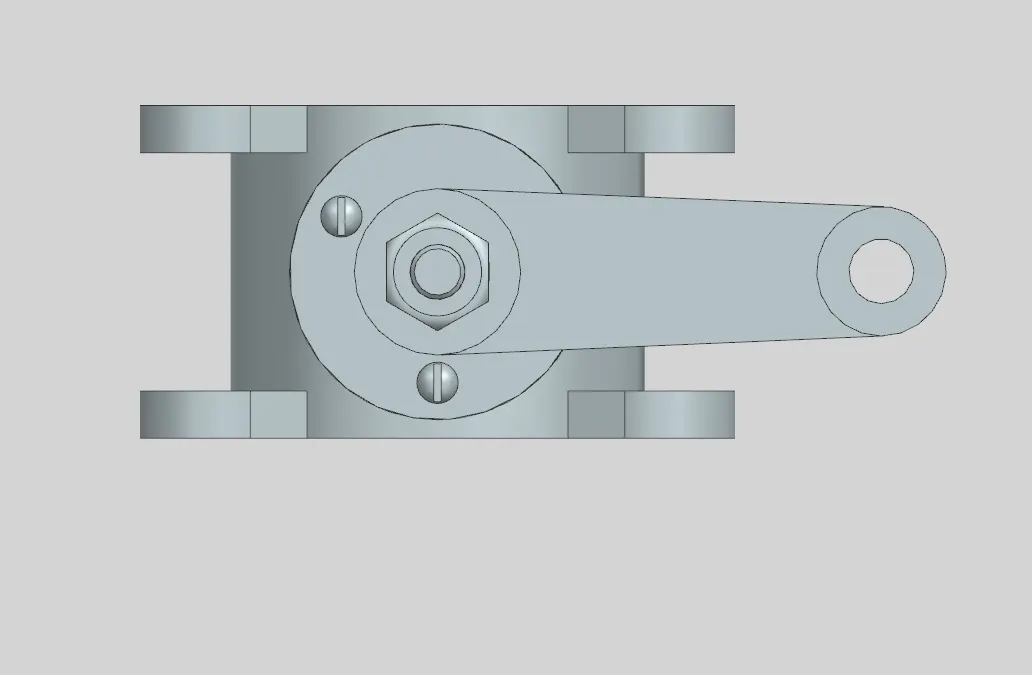
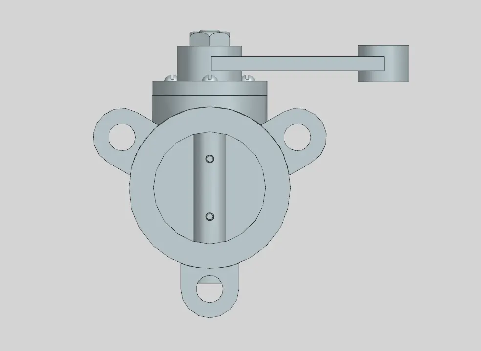
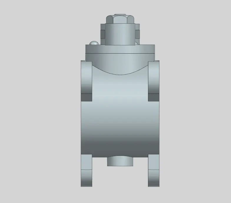
- Using Assembly feature in NX CAD software all the parts saved inthe same folders are added to the assembly one by one Body, Lever, Shaft, Retainer,Disc etc.
- And using the Move option and Assembly Constraints option the different parts Moved and joined together with the help of Align,touch,infer/Axis operations.
- In this way the assembly of Butterfly is arranged in a proper manner.
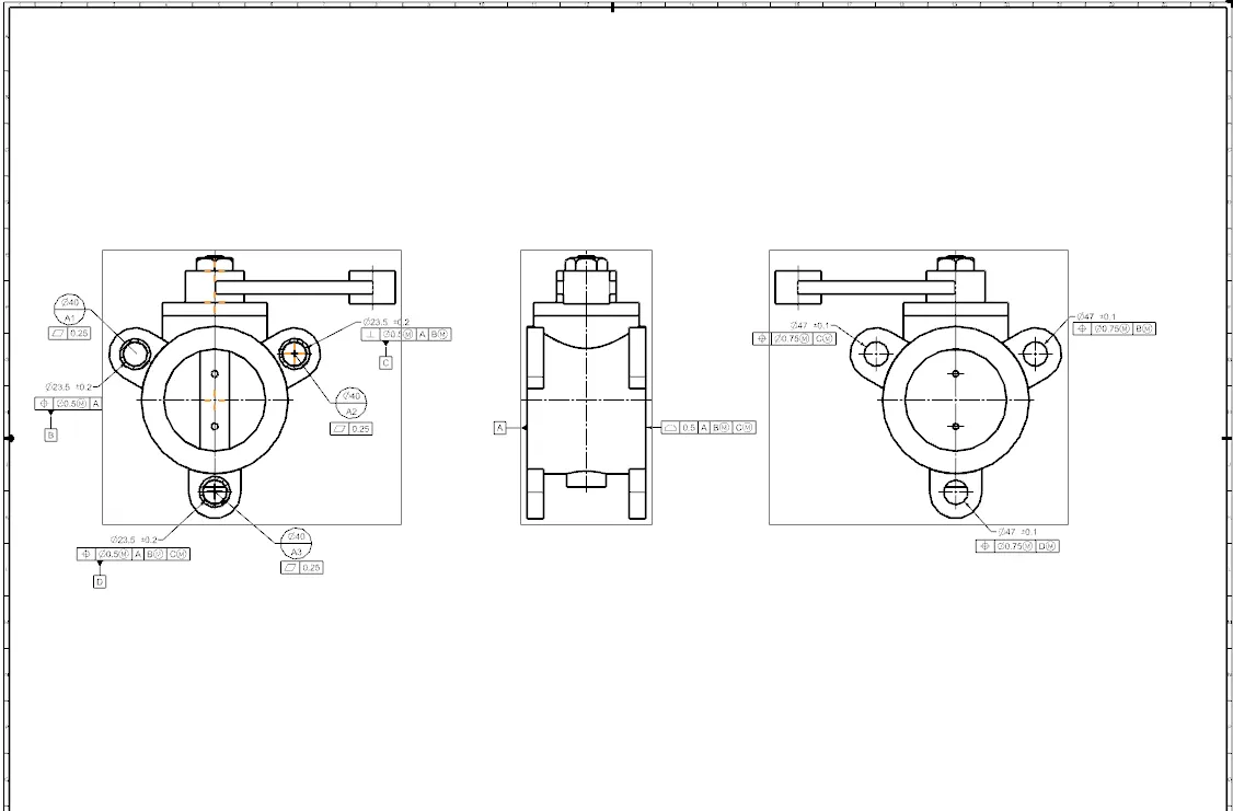
Assembly Drawing of Butterfly Valve-
- Datum target area A1,A2 and A3 is given to the ears of the butterfly valve also flatness tolerances are added to them
- Hole inside Datum target area A2 and A3 is given as Datum B and Datum C with perpendicular tolerance and Position tolerance respectively.
- One more Sub datum D is added and given to the third ear hole with geometric tolerance of position.
- Finally, the tolerances are given to the other functional and important surfaces and features of the Butterfly Valve.
- Int this way GD & T is applieed for this assembly drawing.
Conclusion:
During this project, a butterfly valve is designed and assembled using NX CAD software, and after analysing design and functional feature of the Butterfly Valve the datums are attached and proper tolerances are provided to the diffrent aspects of the assembly. In this way the project is successfully completed.