Week 14 challenge
Final Project (GD&T Using NX CAD)
' BUTTERFLY VALVE ASSEMBLY'
Introduction: Butterfly valves belong to the quarter-turn rotational motion valves family and are used primarily to stop, regulate, or start the flow. The term “butterfly” in a butterfly valve is actually a disk that is connected to a rod. When this rod rotates the disk by 90° the butterfly valve opens or closes. Butterfly valves are popular in the industry because of their lightweight, fast operation, and low costs. These valves use Levers,handles, gears, or automatic actuators for operation as per the requirement.
Smaller-size butterfly valves usually have manual operation whereas larger devices are normally motorized. With high flow capacities, butterfly valves enable the use of smaller units that reduces weight, cost, and space requirement significantly
Components of Butterfly Valve:
1) Body : Butterfly valves are fixed between pipleines using flange couplings.
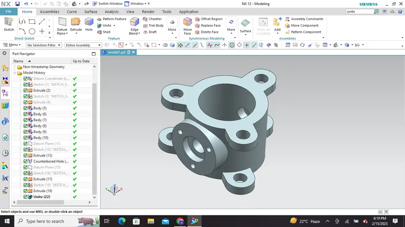
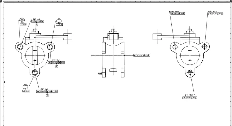
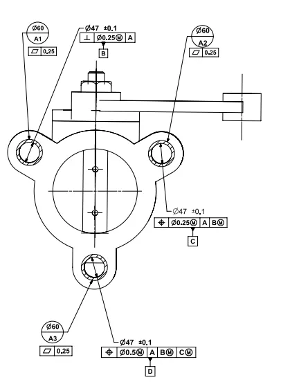
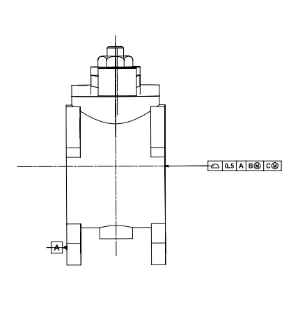
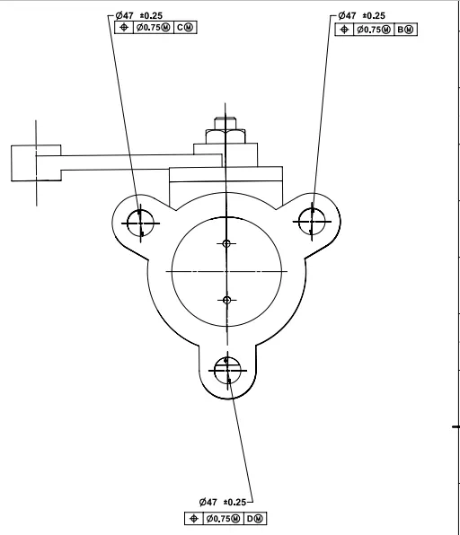
GD & T is applied at the end of the assembly to this body considering it as a main body
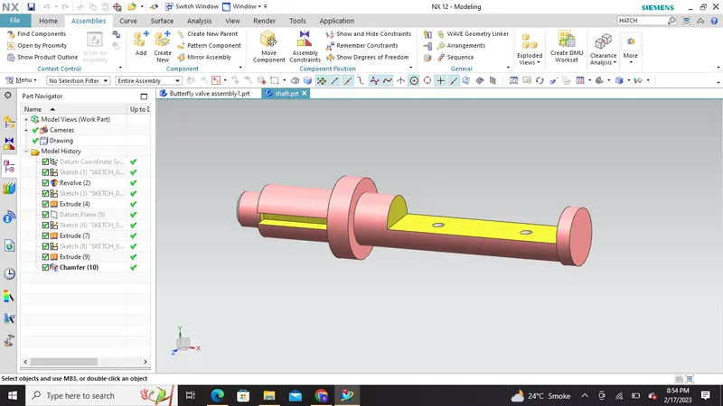
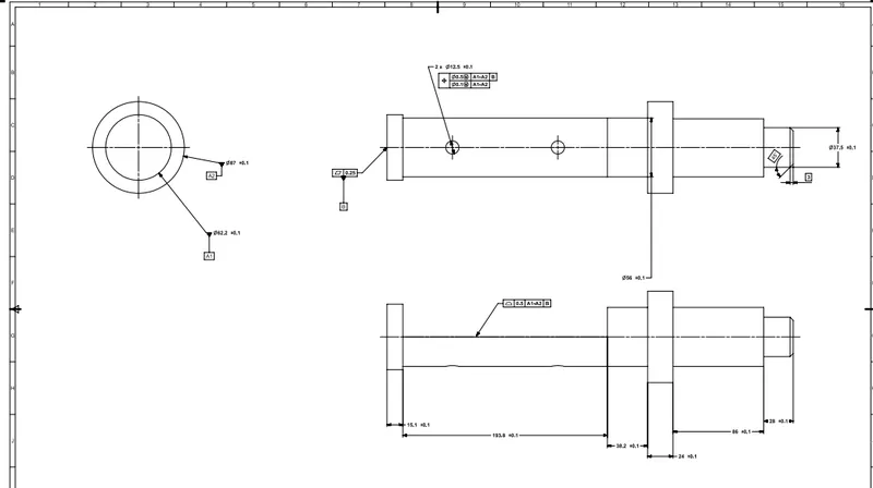
2) SHAFT : The disc/plate, lever and nut are assembled to this shaft.
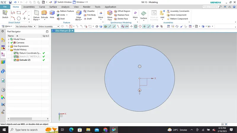
3) DISC : A disc is a flow controlling member of the butterfly valve which is attached to the stem/shaft. The disk is the equivalent of a plug in a plug valve, a gate in a gate valve, or a ball in a ball valve. It functions rotating the disk one-quarter turn or 90 Degrees opens and closes the butterfly valve.
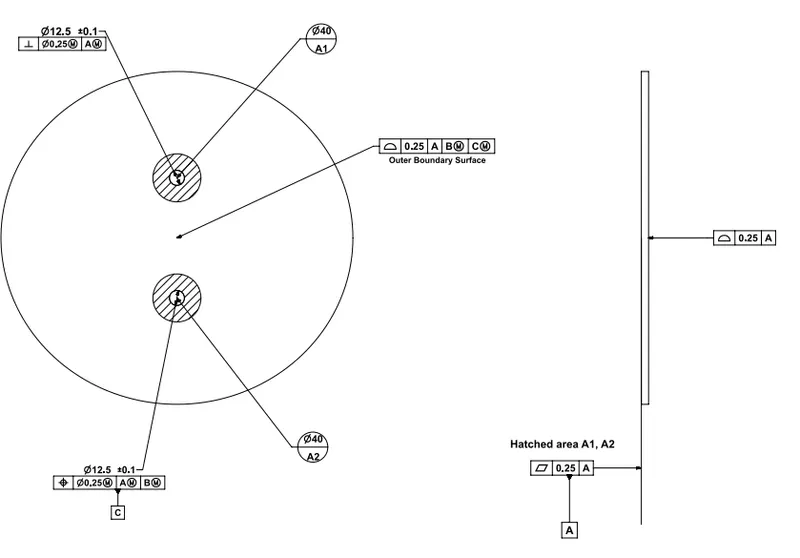
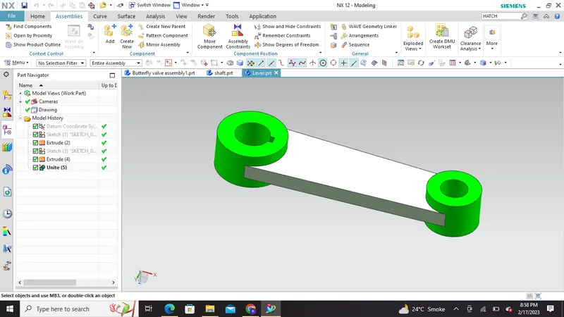
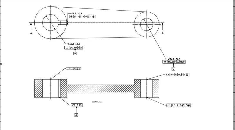
4) LEVER : Lever is mounted at an end of shaft outside the body. Hand lever is usually used in small sized Butterfly valves. It's main function is to open or close the valve.
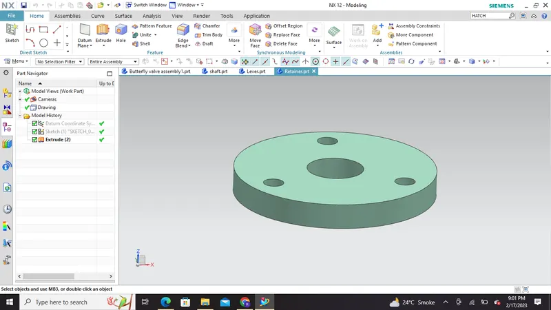
5) RETAINER - Retainer is a kind of washer fixed on the body of butterfly valve.
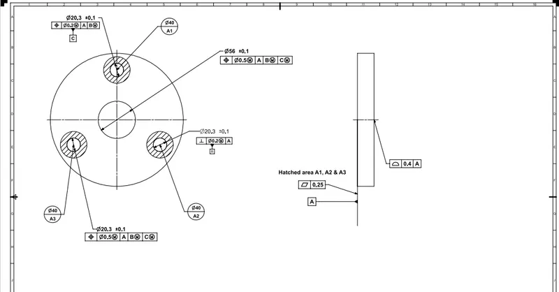
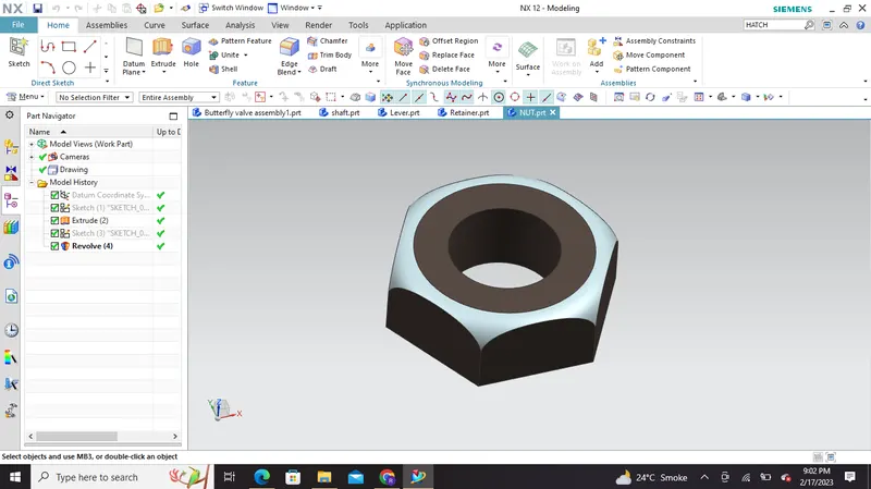
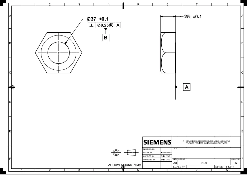
6) NUT :It is fixed at the top end of shaft to keep the lever and retainer on position relative to the body of butterfly valve.
Advantages of using GD&T :
- Simple communication: GD&T allows us to convey substantial information about our part’s design using a relatively small amount of letters, numbers, and symbols. No long paragraphs of explanation is necessary.The ability to communicate efficiently reduces back and forth between us and the contract manufacturing service we are working with.
- Accurate production: Since GD&T is such a precisely articulated system of language, it minimizes ambiguity in the description of a part design. As a result, we can be confident that our part will be manufactured with the highest degree of accuracy and work as intended in the field.
- Known tolerances: GD&T gives manufacturers a clear understanding of the tolerances for a specific part. It provides the maximum amount of tolerance for the part to function properly, which reduces parts complexity so that we aren’t overspending for a minimum tolerance that we may not need.
- Universal language.: We may find ourself in a situation where we want to work with a contract machining company in another country with a spoken language that is different from ours.GD&T is a universal language widely accepted across the world, thereby eliminating frustrating language barriers for overseas production.
- Precise assemblies: If we have two mating parts that need to come together in an assembly GD&T is an excellent way to communicate how this interfacing can best take place. In these situations, GD&T clearly depicts the tolerances of each part so that manufacturers can easily tell if a measurement is off and adjust accordingly.
Assembly: Assembly in any cad software can be followed by two approaches such as:
A) Bottom up Assembly : In this type of approach the parts are created individually in part workbench and then are assembled in assembly workbench with the help of geometrical constraints and other features. In this assembly project i followed bottom up assembly approach.
B) Top down Assembly : In this type of approach the parts are created inside the assembly workbench by starting the product file and then creation of individual parts is carried out and they can be opened separately in part workbench.
However we can also use both types of assembly combination at a same time if some parts are created while others can be created in assembly workbench.
I have used Bottom up assembly method in this project
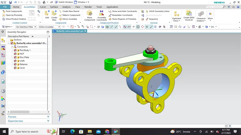
Different Views of the Assembled Body :
1) Isometric view
2) Top View
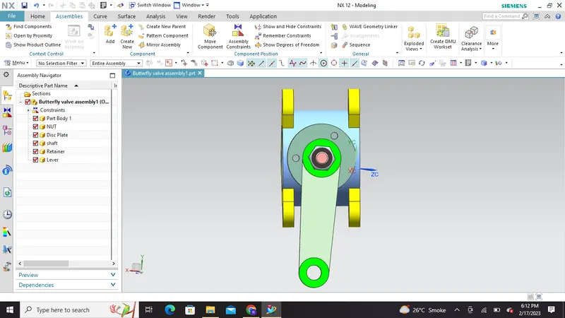
3) Left View
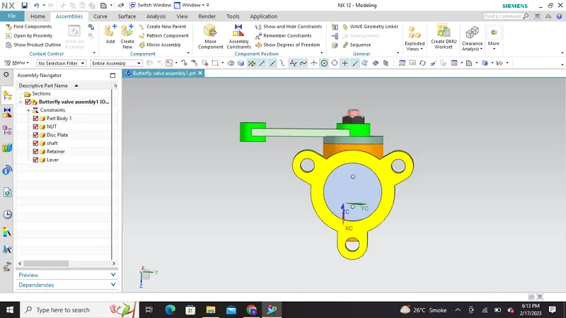
Right view
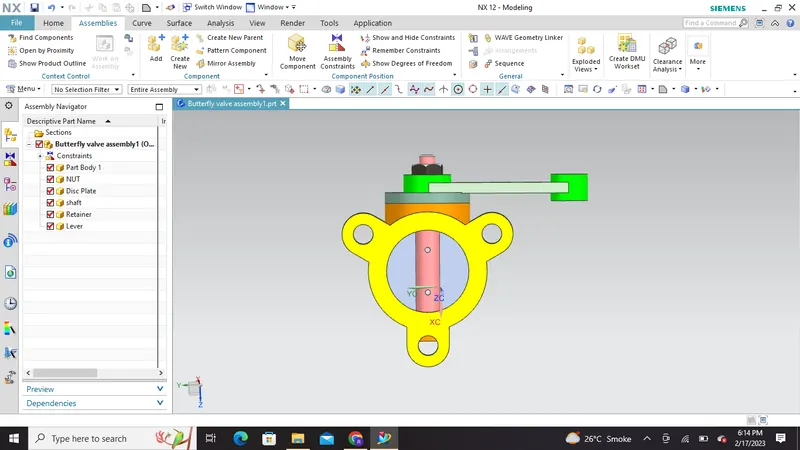
4) Bottom View:
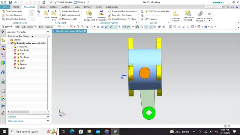
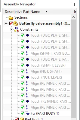
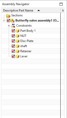
Tree Structure & Assembly constaints:
Drafting using GD&T :
Conclusion: Butterfly valve Final Assembly :
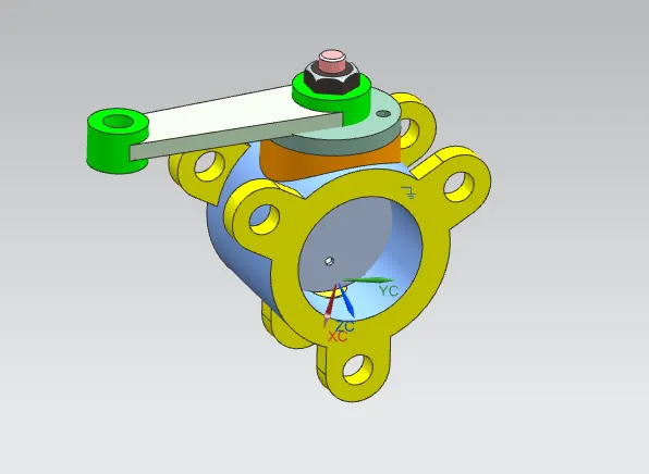
Please find the attachment containing all the Drafting PDF , Part files and main assembly file.
Thank You!