Week 14 challenge
DESIGN OF BUTTERFLY VALVE IN NX CAD AND APPLY GD&T:
OBJECTIVE:
- The aim of the will be working on modelling, assembly, and drafting of a Butterfly Valve. Using the Siemens NX CAD software.
INTRODUCTION:
- NX, formerly known as "unigraphics", is an advanced high-end CAD/CAM/CAE, which has been owned by Siemens PLM Software.
- Working on this project will help you understand how to apply GD&T to the parts so that the parts can be manufactured and assembled properly with proper finish and quality.
DESCRIPTION:
- Software Used:
- NX CAD
- Parts of Butterfly Valve:
- Body.
- Shaft/Stem.
- Disc/Plate.
- Retainer.
- Lever.
- Nut.
Body.
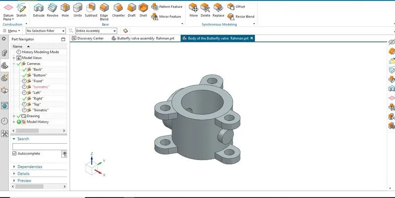
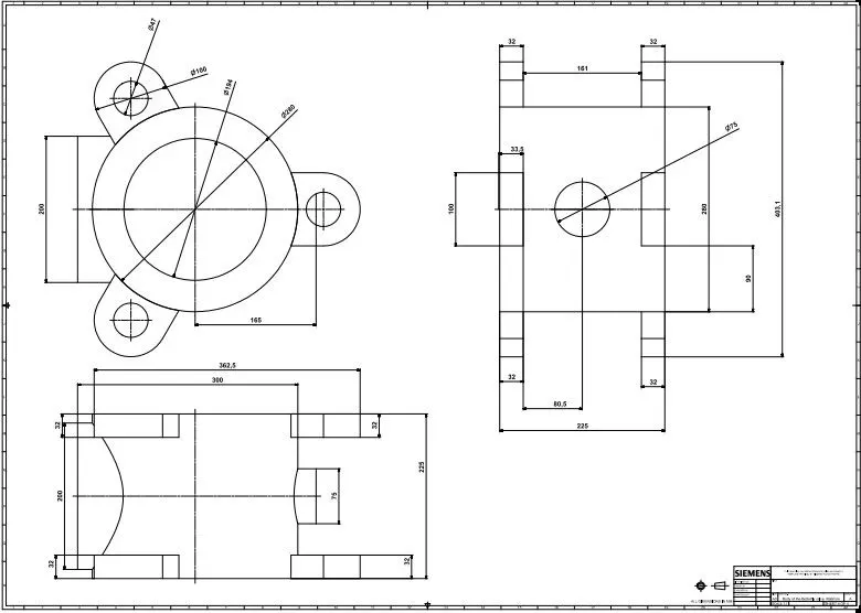
Butterfly valves generally have bodies that fit between two pipe flanges. The most common body designs are lug and wafer. The lug body has protruding lugs that provide bolt holes matching those in the pipe flange. A wafer body does not have protruding lugs. The wafer valve is sandwiched between the pipe flanges, and the flange bolts surround the body.
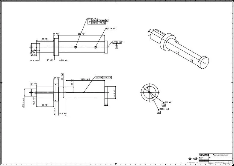
Shaft/Stem.
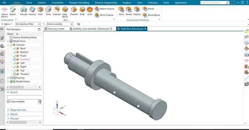
The shaft controls the flow through a pipe by use of a single disc mounted on it which creates a variable orifice. It rotates as the fluid passes through the flow passage.The rotary action of the stem initiated from the power of the actuator is transmitted to the disc, allowing the close and open position of the valve.
Disc/Plate.
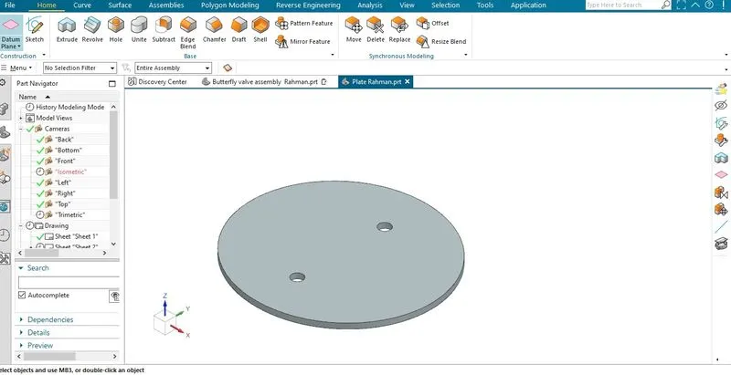
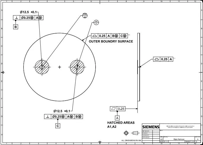
The flow closure member of a butterfly valve is the disc. Rotating the disc one-quarter turn or 90 Degrees opens and closes the butterfly valve.The disk is always in the passageway, but because it is relatively thin, it offers little resistance to flow.
Retainer.
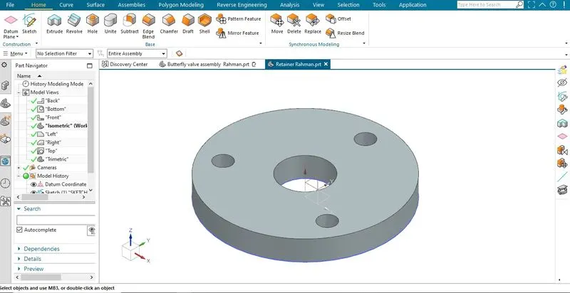
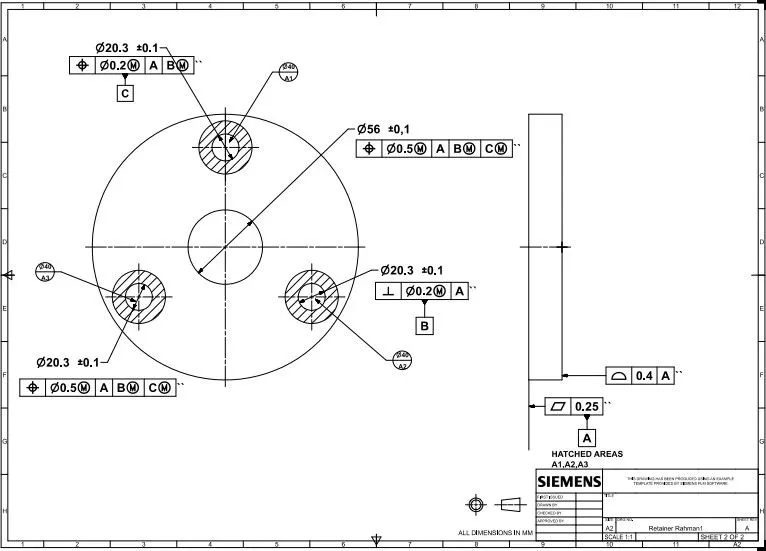
The retainer screws into the valve body to hold the seat in place with pressure and make a simple one piece body Valve assembly.
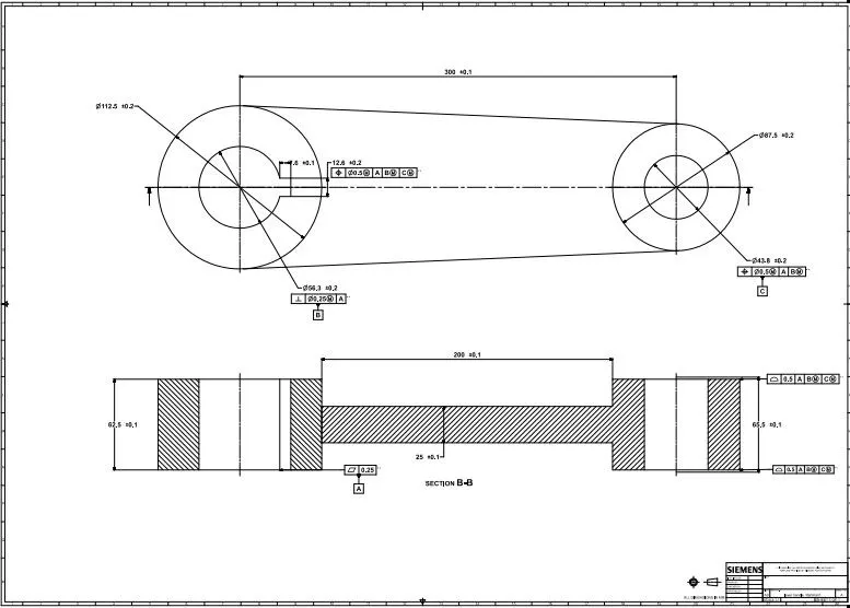
Lever.
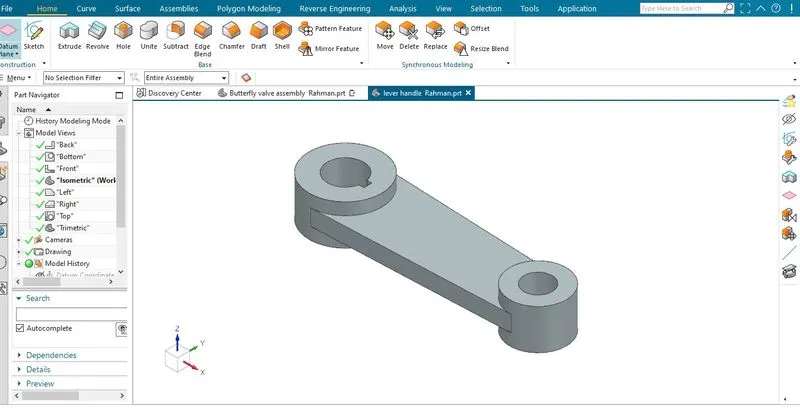
The lever handle operates the valve, but also serves as an indicator for whether the valve is open or closed. When the lever is parallel to the pipe, the valve is open.
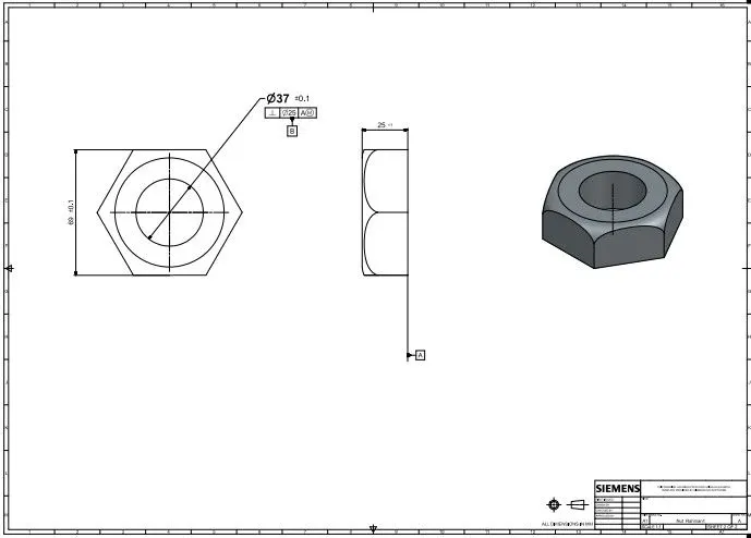
Nut.
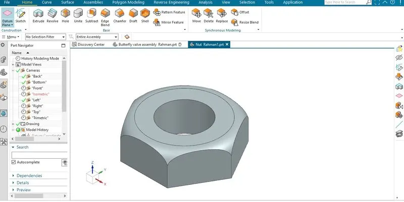
They are small washer-shaped circles that thread onto the outside of the valve shaft down to the rim in order to engage the lever with the shaft.
Butterfly Valve Assembly
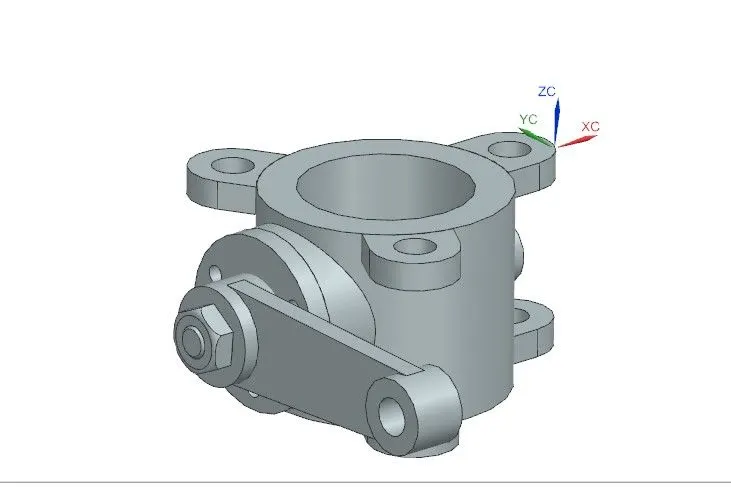
All the parts of the valve were then assembled using various assembly mates such as Touch, Align, Center-axis align, etc. and GD&T was applied to the whole assembly.
- All the Parts of Butterfly Valve:
- Body.
- Shaft/Stem.
- Disc/Plate.
- Retainer.
- Lever.
- Nut.
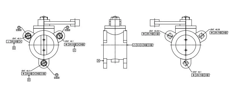
RESULT:
This the different parts of a Butterfly Valve were modelled and GD&T was applied to all the parts and to the assembly using NX CAD.