Week 12 - Symmetry vs Wedge vs HP equation
Objective :
To compare the results of the flow simulation through an open pipe in wedge condition (considering wedge angle `theta` = 1,3,4) and symmetrical condition for (`theta` = 10,25,45) with the results obtained from the analytical solution using Hagen-poiseuille's equation.
Let the length of the pipe be - L
Velocity at the center of the pipe being maximum be - Vm
Dynamic Viscosity of the fluid - `mu`
Radius of the pipe - R
Diameter of the pipe - D
Area of cross section of pipe be - A
Density of the fluid - `rho`
Mean velocity of the fluid - v
Reynold's number - Re
`v = (mu * Re )/(rho*D)` -------- (1)
Analytical calculation:
Let us consider the following parameters :
R = 50 mm
D = 100 mm = 0.1 m
A = 0.031415 `m^2`
The fluid considered is water and all of it's properties are taken at room temperature(25deg. C)
`rho = 997 (kg)/m^3`
`mu = 8.9 **10^-4 Pa.s`
Since the flow is assumed to be laminar flow, the Reynold's number is <2300, hence consider,
Re = 400
Substituting the above values to equation (1),
we get the mean velocity to be
v = 0.0035707 m/s
Analytical maximum velocity Vmax = v * 2
Vmax = 0.007141 m/s
To measure the hydrodynamic length
L = 0.006 * Re * D
L = 0.24 m
Matlab program :
The program below shows the matlab code to generate the blockMeshDict for a given radius and wedge angle for a symmetrical boundary condition.
clear all
close all
clc
theta = input('theta = ');
%Radius in meters
r = 0.05;
%Diameter in meters
d = 0.1;
%Wedge angle in degrees
%theta = 10;
%Reynold's number
Re = 400;
%Length of the pipe
L = ((0.006*Re*d)+0.1);
%Dynamic viscosity
mu = 0.00089;
%Density
rho = 997;
%number of mesh points along the length of the pipe
nl = 100;
%number of mesh points along the radius of the pipe
nr = 50;
%grading scheme along respective axis
x = input('Grading factor along x = ');
y = input('Grading factor along y = ');
z = input('Grading factor along z = ');
%vertices
v0 = [ 0 0 0];
v1 = [0  r*cosd(theta/2) -r*sind(theta/2) ];
v2 = [0  r*cosd(theta/2) r*sind(theta/2) ];
v3 = [L 0 0];
v4 = [L  r*cosd(theta/2) -r*sind(theta/2) ];
v5 = [L  r*cosd(theta/2)  r*sind(theta/2)];

f1 = fopen('blockMeshDict40.txt','w');

fprintf(f1,'FoamFile\n');
fprintf(f1,'{\n');
fprintf(f1,'     version    2.0;\n');
fprintf(f1,'     format     ascii;\n');
fprintf(f1,'     class      dictionary;\n');
fprintf(f1,'     object     blockMeshDict;\n');
fprintf(f1,'}\n');
fprintf(f1,'//**************************************// \n\n');
fprintf(f1,'convertToMeters 1;\n\n');
fprintf(f1,'vertices\n');
fprintf(f1,'(\n\t');
fprintf(f1,'(%.7f %.7f %.7f) //0 \n\t',v0(1),v0(2),v0(3));
fprintf(f1,'(%.7f %.7f %.7f) //1 \n\t',v1(1),v1(2),v1(3));
fprintf(f1,'(%.7f %.7f %.7f) //2 \n\t',v2(1),v2(2),v2(3));
fprintf(f1,'(%.7f %.7f %.7f) //3 \n\t',v3(1),v3(2),v3(3));
fprintf(f1,'(%.7f %.7f %.7f) //4 \n\t',v4(1),v4(2),v4(3));
fprintf(f1,'(%.7f %.7f %.7f) //5 \n\n',v5(1),v5(2),v5(3));
fprintf(f1,');\n\n');

fprintf(f1,'blocks\n');
fprintf(f1,'(\n\t');
fprintf(f1,'hex ( 0 1 2 0 3 4 5 3) (%d 1 %d) simpleGrading (%.2f %.2f %.2f)\n',nl,nr,x,y,z);
fprintf(f1,');\n\n');

fprintf(f1,'edges\n');
fprintf(f1,'(\n\t');
fprintf(f1,'arc 2 1 (0 %.3f 0)\n\t',r);
fprintf(f1,'arc 5 4 (%.3f %.3f 0)\n',L,r);
fprintf(f1,');\n\n');

fprintf(f1,'boundary\n');
fprintf(f1,'(\n\t');

fprintf(f1,'axis\n\t');
fprintf(f1,'{\n\t\t');
fprintf(f1,'type empty;\n\t\t');
fprintf(f1,'faces\n\t\t');
fprintf(f1,'(\n\t\t\t');
fprintf(f1,'(0 3 3 0)\n\t\t');
fprintf(f1,');\n\t');
fprintf(f1,'}\n\n\t');

fprintf(f1,'inlet\n\t');
fprintf(f1,'{\n\t\t');
fprintf(f1,'type patch;\n\t\t');
fprintf(f1,'faces\n\t\t');
fprintf(f1,'(\n\t\t\t');
fprintf(f1,'(0 2 1 0)\n\t\t');
fprintf(f1,');\n\t');
fprintf(f1,'}\n\n\t');

fprintf(f1,'outlet\n\t');
fprintf(f1,'{\n\t\t');
fprintf(f1,'type patch;\n\t\t');
fprintf(f1,'faces\n\t\t');
fprintf(f1,'(\n\t\t\t');
fprintf(f1,'(3 4 5 3)\n\t\t');
fprintf(f1,');\n\t');
fprintf(f1,'}\n\n\t');

fprintf(f1,'fixedWalls\n\t');
fprintf(f1,'{\n\t\t');
fprintf(f1,'type wall;\n\t\t');
fprintf(f1,'faces\n\t\t');
fprintf(f1,'(\n\t\t\t');
fprintf(f1,'(1 2 5 4)\n\t\t');
fprintf(f1,');\n\t');
fprintf(f1,'}\n\n\t');

fprintf(f1,'front\n\t');
fprintf(f1,'{\n\t\t');
fprintf(f1,'type symmetry;\n\t\t');
fprintf(f1,'faces\n\t\t');
fprintf(f1,'(\n\t\t\t');
fprintf(f1,'(0 3 5 2)\n\t\t');
fprintf(f1,');\n\t');
fprintf(f1,'}\n\n\t');

fprintf(f1,'back\n\t');
fprintf(f1,'{\n\t\t');
fprintf(f1,'type symmetry;\n\t\t');
fprintf(f1,'faces\n\t\t');
fprintf(f1,'(\n\t\t\t');
fprintf(f1,'(0 1 4 3)\n\t\t');
fprintf(f1,');\n\t');
fprintf(f1,'}\n');
fprintf(f1,');\n\n');

fprintf(f1,'mergePatchPairs\n\n');
fprintf(f1,'(\n\n');
fprintf(f1,');\n\n');

fprintf(f1,'//**************************************//');

fclose(f1)
controlDict file :
/*--------------------------------*- C++ -*----------------------------------*\
  =========                 |
  \\      /  F ield         | OpenFOAM: The Open Source CFD Toolbox
   \\    /   O peration     | Website:  https://openfoam.org
    \\  /    A nd           | Version:  8
     \\/     M anipulation  |
\*---------------------------------------------------------------------------*/
FoamFile
{
    version     2.0;
    format      ascii;
    class       dictionary;
    location    "system";
    object      controlDict;
}
// * * * * * * * * * * * * * * * * * * * * * * * * * * * * * * * * * * * * * //

application     icoFoam;

startFrom       startTime;

startTime       0;

stopAt          endTime;

endTime         30;

deltaT          1e-3;

writeControl    timeStep;

writeInterval   10;

purgeWrite      0;

writeFormat     ascii;

writePrecision  6;

writeCompression off;

timeFormat      general;

timePrecision   6;

runTimeModifiable true;


// ************************************************************************* //
Transport properties:
/*--------------------------------*- C++ -*----------------------------------*\
  =========                 |
  \\      /  F ield         | OpenFOAM: The Open Source CFD Toolbox
   \\    /   O peration     | Website:  https://openfoam.org
    \\  /    A nd           | Version:  8
     \\/     M anipulation  |
\*---------------------------------------------------------------------------*/
FoamFile
{
    version     2.0;
    format      ascii;
    class       dictionary;
    location    "constant";
    object      transportProperties;
}
// * * * * * * * * * * * * * * * * * * * * * * * * * * * * * * * * * * * * * //

nu              [0 2 -1 0 0 0 0] 0.0000089267;


// ************************************************************************* //
Initial pressure condition:
/*--------------------------------*- C++ -*----------------------------------*\
  =========                 |
  \\      /  F ield         | OpenFOAM: The Open Source CFD Toolbox
   \\    /   O peration     | Website:  https://openfoam.org
    \\  /    A nd           | Version:  8
     \\/     M anipulation  |
\*---------------------------------------------------------------------------*/
FoamFile
{
    version     2.0;
    format      ascii;
    class       volScalarField;
    object      p;
}
// * * * * * * * * * * * * * * * * * * * * * * * * * * * * * * * * * * * * * //

dimensions      [0 2 -2 0 0 0 0];

internalField   uniform 0;

boundaryField
{
    inlet
    {
        type            zeroGradient;
    }

    fixedWalls
    {
        type            zeroGradient;
    }
    outlet
    {
        type            zeroGradient;
        value           $internalField;
    }

    axis
    {
        type            empty;
    }
    front
    {
        type            symmetry;
    }
    back
    {
        type            symmetry;
    }
}

// ************************************************************************* //
Initial velocity condition :
/*--------------------------------*- C++ -*----------------------------------*\
  =========                 |
  \\      /  F ield         | OpenFOAM: The Open Source CFD Toolbox
   \\    /   O peration     | Website:  https://openfoam.org
    \\  /    A nd           | Version:  8
     \\/     M anipulation  |
\*---------------------------------------------------------------------------*/
FoamFile
{
    version     2.0;
    format      ascii;
    class       volVectorField;
    object      U;
}
// * * * * * * * * * * * * * * * * * * * * * * * * * * * * * * * * * * * * * //

dimensions      [0 1 -1 0 0 0 0];

internalField   uniform (0.0035707 0 0);

boundaryField
{
    inlet
    {
        type            fixedValue;
        value		 $internalField;
    }

    fixedWalls
    {
        type            fixedValue;
        value           uniform (0 0 0);
    }
    outlet
    {
        type            zeroGradient;

    }

    axis
    {
        type            empty;
    }
    front
    {
        type            symmetry;
    }
    back
    {
        type            symmetry;
    }
}

// ************************************************************************* //
blockMeshDict file for symmetry condition with an angle of 10 degrees:
FoamFile
{
     version    2.0;
     format     ascii;
     class      dictionary;
     object     blockMeshDict;
}
//**************************************//

convertToMeters 1;

vertices
(
	(0.0000000 0.0000000 0.0000000) //0
	(0.0000000 0.0498097 -0.0043578) //1
	(0.0000000 0.0498097 0.0043578) //2
	(0.3400000 0.0000000 0.0000000) //3
	(0.3400000 0.0498097 -0.0043578) //4
	(0.3400000 0.0498097 0.0043578) //5

);

blocks
(
	hex ( 0 1 2 0 3 4 5 3) (100 1 50) simpleGrading (1.00 1.00 1.00)
);

edges
(
	arc 2 1 (0 0.050 0)
	arc 5 4 (0.340 0.050 0)
);

boundary
(
	axis
	{
		type empty;
		faces
		(
			(0 3 3 0)
		);
	}

	inlet
	{
		type patch;
		faces
		(
			(0 2 1 0)
		);
	}

	outlet
	{
		type patch;
		faces
		(
			(3 4 5 3)
		);
	}

	fixedWalls
	{
		type wall;
		faces
		(
			(1 2 5 4)
		);
	}

	front
	{
		type symmetry;
		faces
		(
			(0 3 5 2)
		);
	}

	back
	{
		type symmetry;
		faces
		(
			(0 1 4 3)
		);
	}
);

mergePatchPairs

(

);

//**************************************//
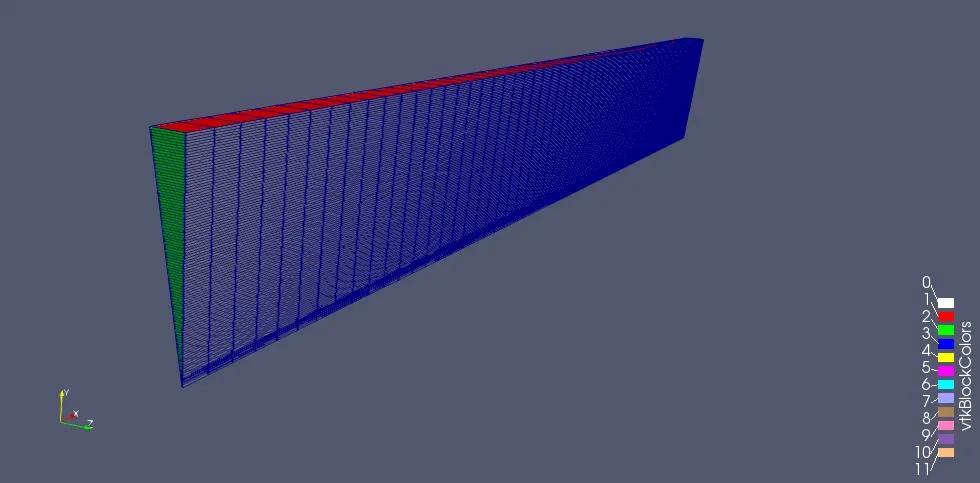
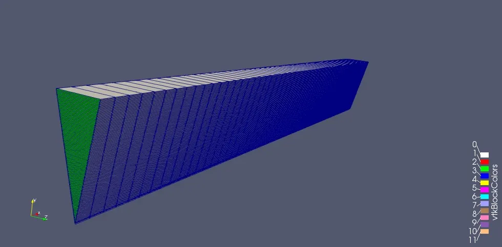
mesh:
The mesh generated is of grading 1 in all direction.
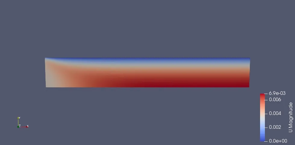
Fully developed profile:
The image below shows the velocity contour inside the pipe after the vector field inside the pipe calculated
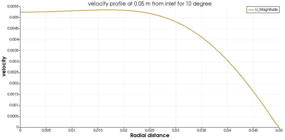
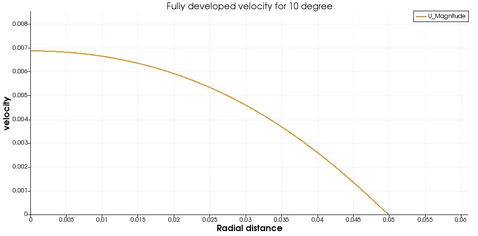
Velocity plots
In the images below we can see the plot of the velocity profile at the inlet and the outlet and it can be observed that the velocity is smoothened out the the end and considering that the flow is laminar, it checks out with Hagen-Poiseuille's flow equation and it can be observed the maximum velocity is at the centre and the velocity decreases as we move towards the walls of the pipe.
blockMeshDict file for symmetry condition with an angle of 25 degrees:
FoamFile
{
     version    2.0;
     format     ascii;
     class      dictionary;
     object     blockMeshDict;
}
//**************************************//

convertToMeters 1;

vertices
(
	(0.0000000 0.0000000 0.0000000) //0
	(0.0000000 0.0488148 -0.0108220) //1
	(0.0000000 0.0488148 0.0108220) //2
	(0.3400000 0.0000000 0.0000000) //3
	(0.3400000 0.0488148 -0.0108220) //4
	(0.3400000 0.0488148 0.0108220) //5

);

blocks
(
	hex ( 0 1 2 0 3 4 5 3) (100 1 50) simpleGrading (1.00 1.00 1.00)
);

edges
(
	arc 2 1 (0 0.050 0)
	arc 5 4 (0.340 0.050 0)
);

boundary
(
	axis
	{
		type empty;
		faces
		(
			(0 3 3 0)
		);
	}

	inlet
	{
		type patch;
		faces
		(
			(0 2 1 0)
		);
	}

	outlet
	{
		type patch;
		faces
		(
			(3 4 5 3)
		);
	}

	fixedWalls
	{
		type wall;
		faces
		(
			(1 2 5 4)
		);
	}

	front
	{
		type symmetry;
		faces
		(
			(0 3 5 2)
		);
	}

	back
	{
		type symmetry;
		faces
		(
			(0 1 4 3)
		);
	}
);

mergePatchPairs

(

);

//**************************************//
mesh:
The mesh generated is of grading 1 in all direction.
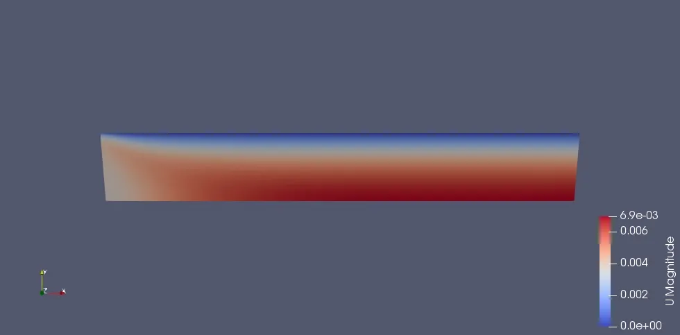
Fully developed profile:
The image below shows the velocity contour inside the pipe after the vector field inside the pipe calculated
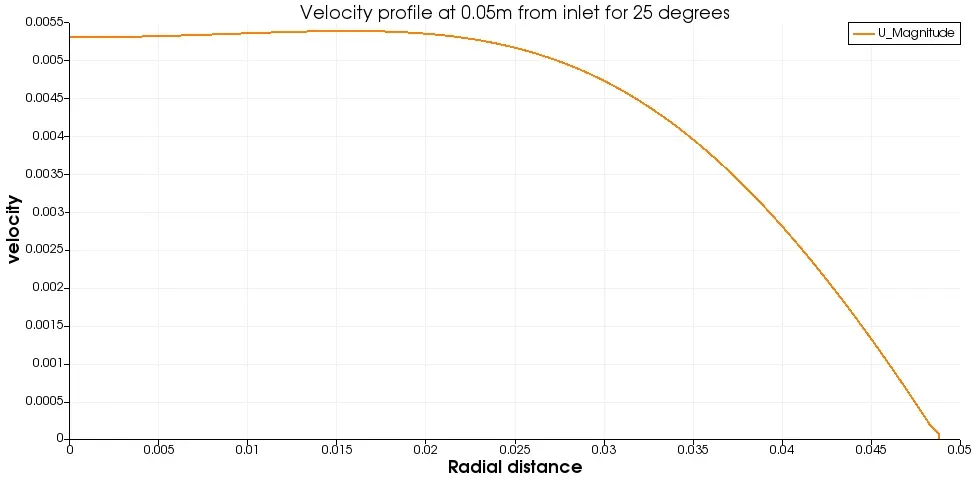
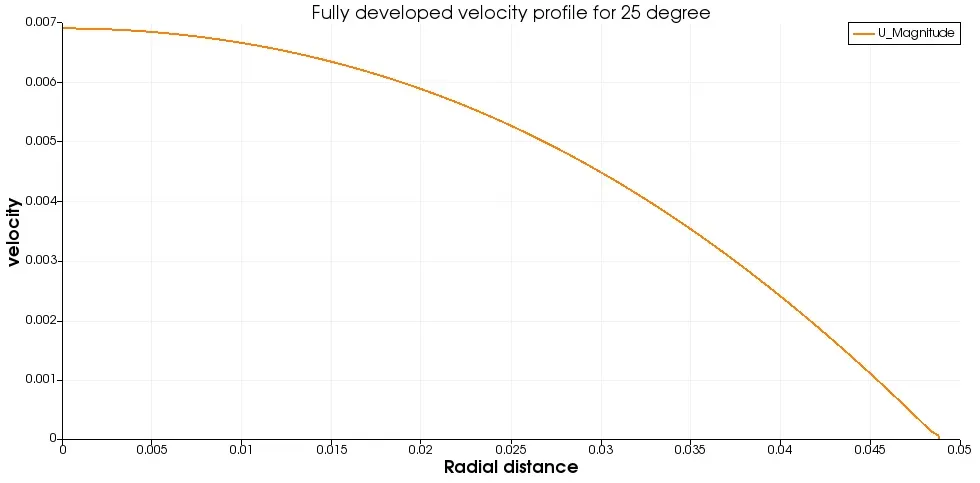
Velocity plots
In the images below we can see the plot of the velocity profile at the inlet and the outlet and it can be observed that the velocity is smoothened out the the end and considering that the flow is laminar, it checks out with Hagen-Poiseuille's flow equation and it can be observed the maximum velocity is at the centre and the velocity decreases as we move towards the walls of the pipe.
blockMeshDict file for symmetry condition with an angle of 45 degrees:
FoamFile
{
     version    2.0;
     format     ascii;
     class      dictionary;
     object     blockMeshDict;
}
//**************************************//

convertToMeters 1;

vertices
(
	(0.0000000 0.0000000 0.0000000) //0
	(0.0000000 0.0469846 -0.0171010) //1
	(0.0000000 0.0469846 0.0171010) //2
	(0.3400000 0.0000000 0.0000000) //3
	(0.3400000 0.0469846 -0.0171010) //4
	(0.3400000 0.0469846 0.0171010) //5

);

blocks
(
	hex ( 0 1 2 0 3 4 5 3) (100 1 50) simpleGrading (1.00 1.00 1.00)
);

edges
(
	arc 2 1 (0 0.050 0)
	arc 5 4 (0.340 0.050 0)
);

boundary
(
	axis
	{
		type empty;
		faces
		(
			(0 3 3 0)
		);
	}

	inlet
	{
		type patch;
		faces
		(
			(0 2 1 0)
		);
	}

	outlet
	{
		type patch;
		faces
		(
			(3 4 5 3)
		);
	}

	fixedWalls
	{
		type wall;
		faces
		(
			(1 2 5 4)
		);
	}

	front
	{
		type symmetry;
		faces
		(
			(0 3 5 2)
		);
	}

	back
	{
		type symmetry;
		faces
		(
			(0 1 4 3)
		);
	}
);

mergePatchPairs

(

);

//**************************************//
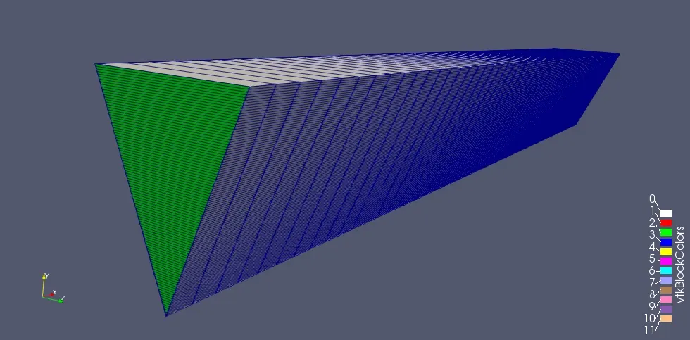
mesh:
The mesh generated is of grading 1 in all direction.
Fully developed profile:
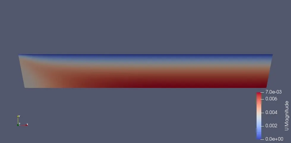
The image below shows the velocity contour inside the pipe after the vector field inside the pipe calculated
Velocity plots
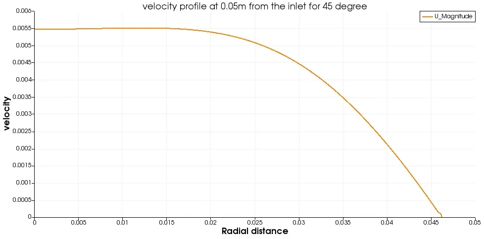
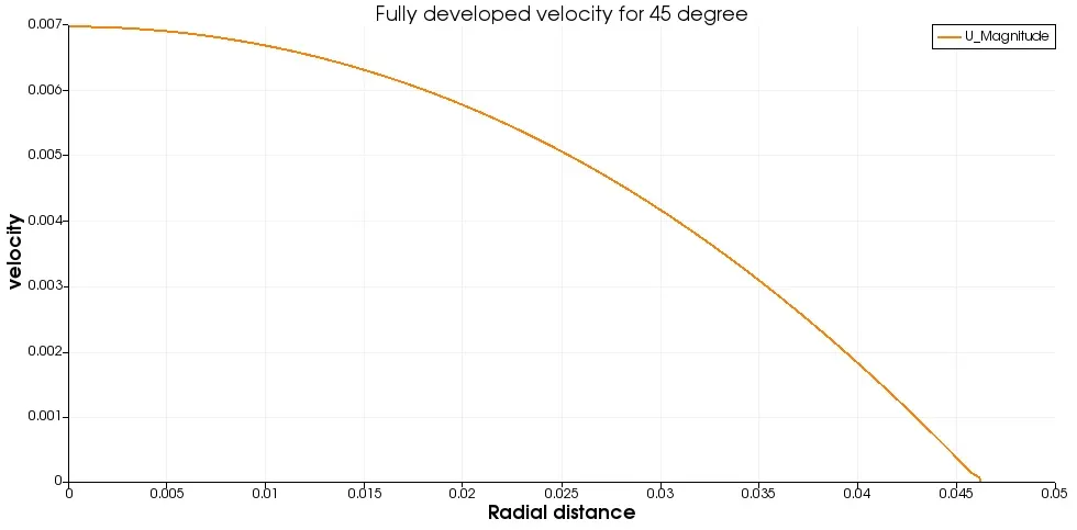
In the images below we can see the plot of the velocity profile at the inlet and the outlet and it can be observed that the velocity is smoothened out the the end and considering that the flow is laminar, it checks out with Hagen-Poiseuille's flow equation and it can be observed the maximum velocity is at the centre and the velocity decreases as we move towards the walls of the pipe.
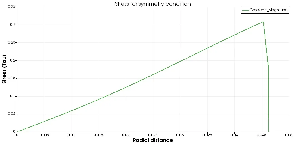
Shear stress plot:
The image below shows the plot on how the shear stress on the fluid flowing is varying along the radial length of the pipe. It can be observed that it gradually increases while moving from the centre of the pipe radially. As we start to approach the pipe wall the shear stress increases.
Comparison :
| `theta` in degrees | Maximum velocity in m/s |
Error = (Analytical result - simulation result) |
Percentage error | |
| Wedge | 1 | 0.00686762 | 0.00027362 | 3.831 |
| Wedge | 3 | 0.00686716 | 0.00027408 | 3.837 |
| Wedge | 4 | 0.00686603 | 0.00027521 | 3.853 |
| Symmetry | 10 | 0.00686649 | 0.00027475 | 3.847 |
| Symmetry | 25 | 0.00690137 | 0.00023987 | 3.358 |
| Symmetry | 45 | 0.00697093 | 0.00017031 | 2.384 |
| Analytical | - | 0.00714124 | - | - |
Conclusion:
All of the above cases were simulated under same parameters. The total simulation time was from 0 to 10 seconds with write interval at 10 and dt of 0.001s to keep the CFL number below 0.5, hence keeping the conditions and test cases consistent.
It can be observed that the symmetry boundary condition is closer to analytical solution compared to that of wedge boundary condition. As the magnitude of angle increases the error becomes less hence more accurate solution.