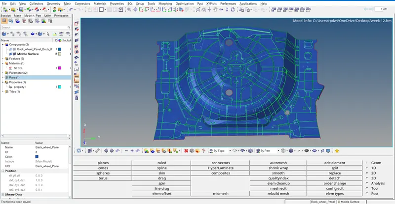
Week 12:Project 2-Meshing of Rear Wheel Holder challenge
Project 2-Meshing of Rear Wheel Holder challenge
Objective: Meshing of rear wheel holder using hypermesh and assigning suitable thickness to them.
OBJECTIVE-
- Import cad model
- Clean up the geometry.
- Extract Mid-Surface for the geometry.
- Meshing according to given quality criteria.
- Assign thickness to the component.
- Conclusion
- Learning outcomes
- Final image
Theory:
A spare tyre or stepny is an additional tire/tyre carried in a motor vehicle as a replacement for one that goes flat, has a blowout, or has another emergency.
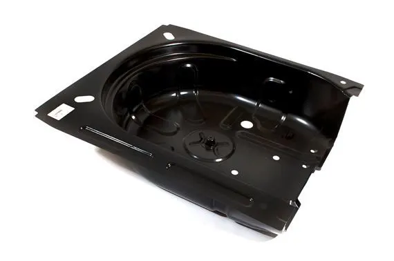
About this component-
- The component which is given to us is a car stepney spare wheel floor panel.
- This is a sheet metal component.
- For the plastic and sheet metal component with the thickness less than 6mm at this case we have to take a midsurface in order to mesh the component.
- Sheet metal is a metal formed by an industrial process into thin, flat pieces, sheet metal is one of the fundametal forms used in metal working.
- And it can also be deformed into various types of shapes.
- Countless everyday objets are fabricated from sheet metal.
- Thickness can vary significantly, extremely thin sheets are considered as foil or leaf.
- And pieces thicker than 6mm are considered as plate steel or Structural steel.
PROCEDURE:
- Import cad model:-
(Files-> import-> geometry-> iges format -> select required file-> import)
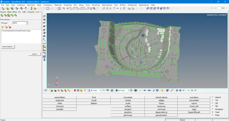
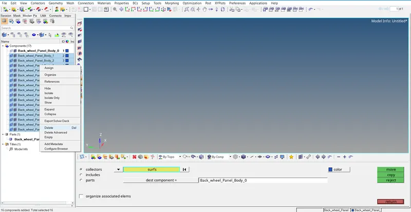
In below image having one part sof first attatched two parts into one by using (Tool>Orgainse>Surfaqce by displayed>male current component>Move)
Also delete unwanted surface by using (Delete>Select Surface >delete)
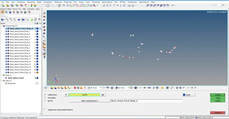
As below image once all surface move into one part so delete all the empty part.
2) Extract Mid-Surface for the geometry:-
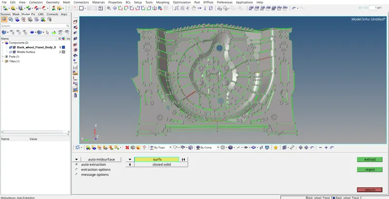
The next step is to extract the mid surface. As the given component is made up of material named "Sheet metal", it will have the same thicknesses in most of the cases. So, The midsurface can be extracted automaically. This is done by
selecting the mid surface option from the geometry panel.

The option used in this project to extract the mid surface is "Offset+Planes+sweep". The extracted mid surface appears in the graphical display
Midsurface extraction is the next step after geometry cleanup and for that, goto (Geom > midsurface > extraction options >Offset+Planes+sweep> auto extraction > surfs > displayed > extract)
3) Geometry clean up:
Surface patch up, creating new surfaces, eleminating of triple cons in unwanted area, converting single cons to double cons in necessary area are comes under geometry cleanup phase.
The rear wheel holder is a plastic component and it has a uniform thickess in it and then the model is cleaned. The cleaning process consists of
closing the holes below 3mm,
toggeling the unwanted lines in the surfaces,
defeaturing the small dia fillet areas,
splitting the surfaces into parts,
filling the empty surfaces,
add/remove the points in the lines,
delete the unwanted surfaces.
There are many useful tools present in the Hypermesh to aviod errors in the model during meshing. The main tool we used in the model is Geometry--->quick edit. The shortcut used for the quick edit tab is F11 key from the keyboard.
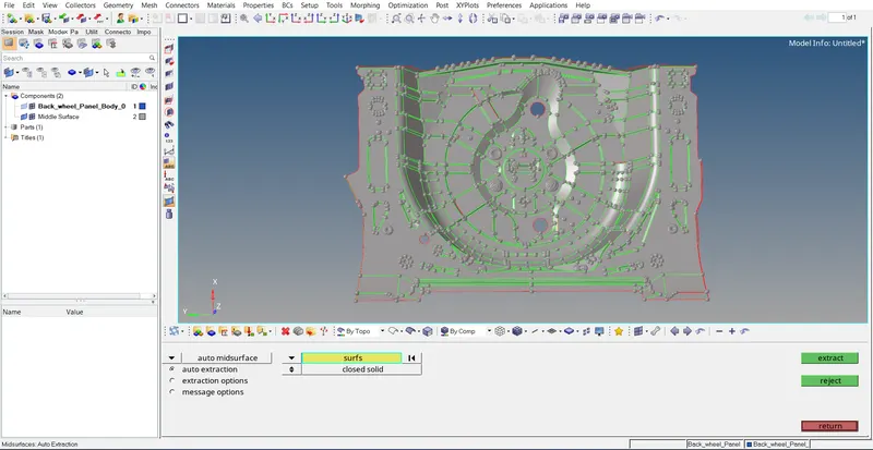
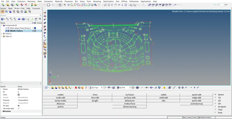
As below image to see gemoterycal error by using wireframe on.
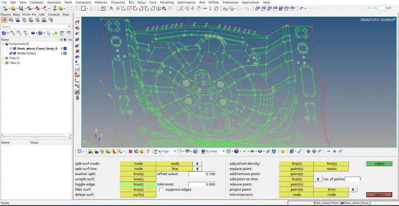
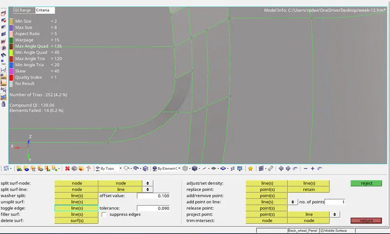
The trim lines in the curved surface in not fully connected to the surfaces and this makes some errors while meshing. To avoid this type of errors split surf-node/split surf-line potion is used. The first option is used to connect two nodes and the second option is used to connect straight line selected.
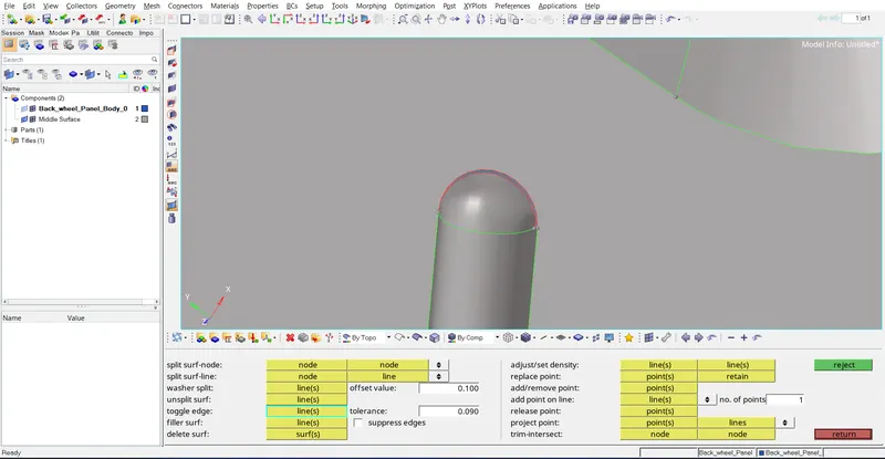
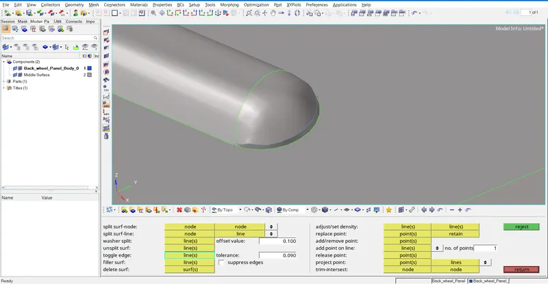
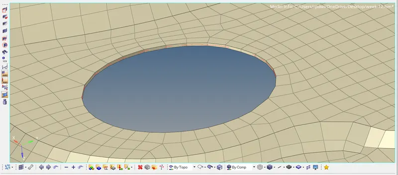
The red line indicates that the line is not shared with the adjacent line and it is called as free edges. To avoid this toggle edge options is used. After togglling the lines the red line is changed to green shared line.
By using the filler surf option the surface is filled. There is also another option used to create surfaces in the missing surface
Geometry--->surfaces, option is used.
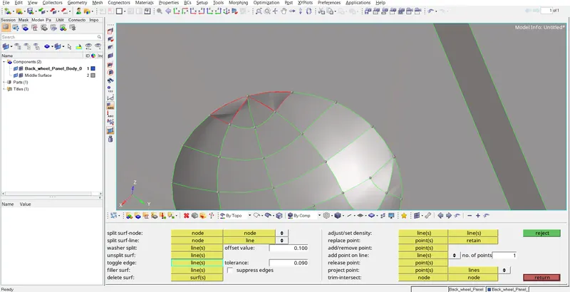
In below image surface not present to fill the surfece by using (Geom>Surface >Ruled >Select two line>Create )
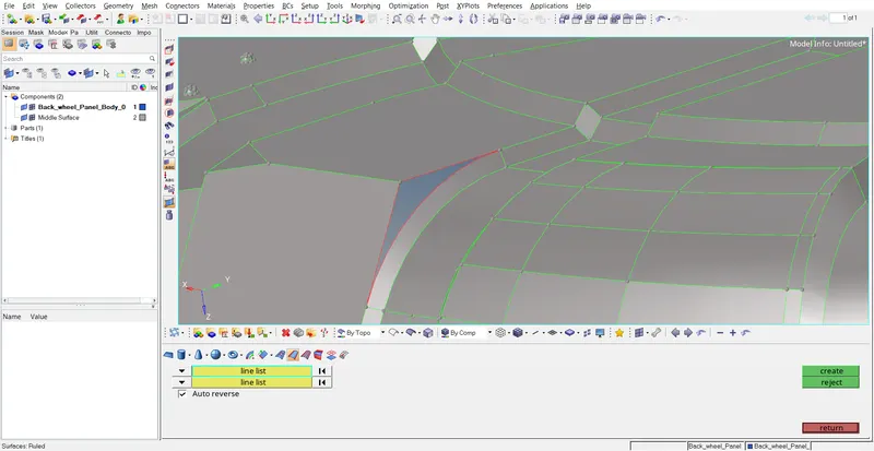
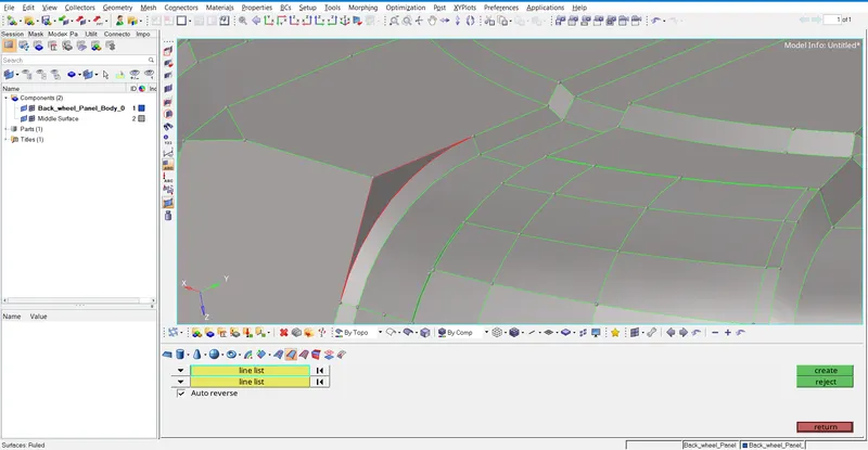
Surface created
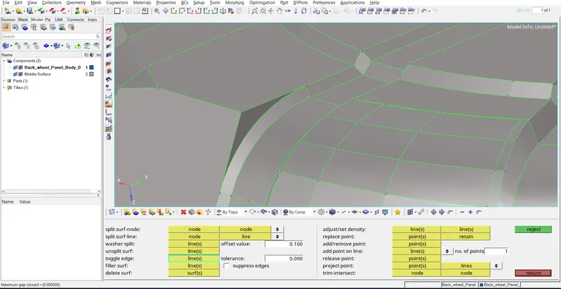
Under visualization options we can see there are four types of edges which are
1) Red color for free edge
2) Green for shared edge
3) Blue for suppressed edge
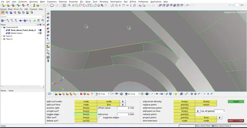
4) Yellow for non-manifold(t-joints)
below image yellow colour present because t-joint avalabile remove this by using first relese the point than remove unwanted point and than toggle the line by using tool (Geom>Quik edit)
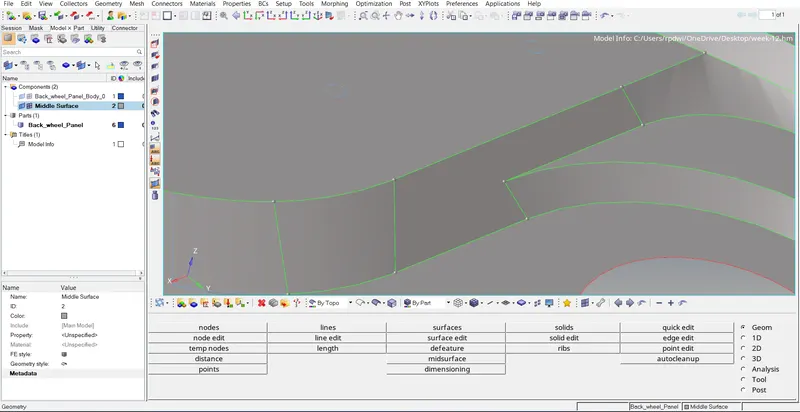
below image no geometry error present to check this by using Wireframe on
4) Meshing according to given quality criteria:
Shell meshing is achieved after skin extraction but we do not mid surface all components based on requirements we should also be doing volumetric mesh.
For casting & molding products we generally go with solid meshing.
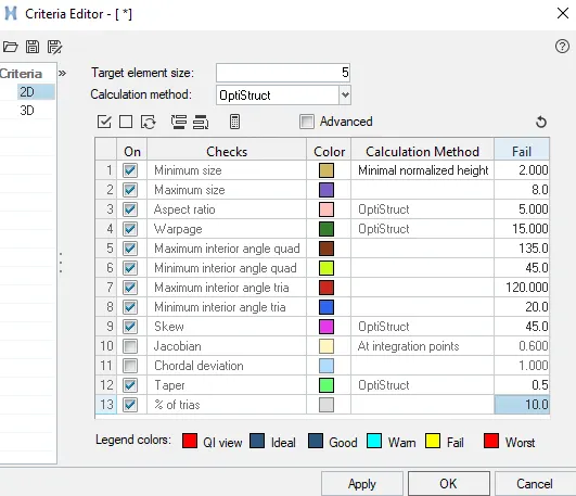
For meshing the target element length is 5mm, minimum length is 2mm, maximum length is 8mm. The quality criteria file is inputted to the model. The command used for the automesh is 2D--->automesh. The shortcut used for the automeshing is F12.

The meshing is not done for the whole component in a single shot. Rather than the surfaces are splitted with the lines and seperated into small surfaces. Then the small surfaces are meshed one by one. This makes the mesh flow even in all places.

The density of the mesh is very important. when it is subjected for some external force or shock wave if the mesh is so denser the time step may affected. So the mesh density should be so finer in way to avoid some errors. The density option in automesh option used for adjusting the density of the mesh.

This option is used to modify the style of the mesh and also modify the mesh in the complex areas.
TOOLS USED TO EDIT THE MESH:
To make the mesh better some tools are used they are smoothing, rebuild mesh, quality index, element cleanup, replace, project, edit element, translate, quick edit, mask are used.
Smoothing:
The process of aligning the set of elements in a proper flow. the command used for smoothing is 2D--->smoothing. The shortcut key for smoothing is Shift+F12.
Rebuild mesh:
This option is associated with the quality criteria file and this option automatically modifies the mesh with respect to the surface. This option is only used in the complex regions that the normal automesh is not working properly. The command used for rebuild mesh is
2D--->rebuild mesh.

Quality index:
This tab is used for editing a elements quality parametres like min length, max length, trai elements etc.

Replace panel: Use the Replace panel to relocate one node to the position of another or manually equivalence two nodes. The shortcut used for the replace option is F3.
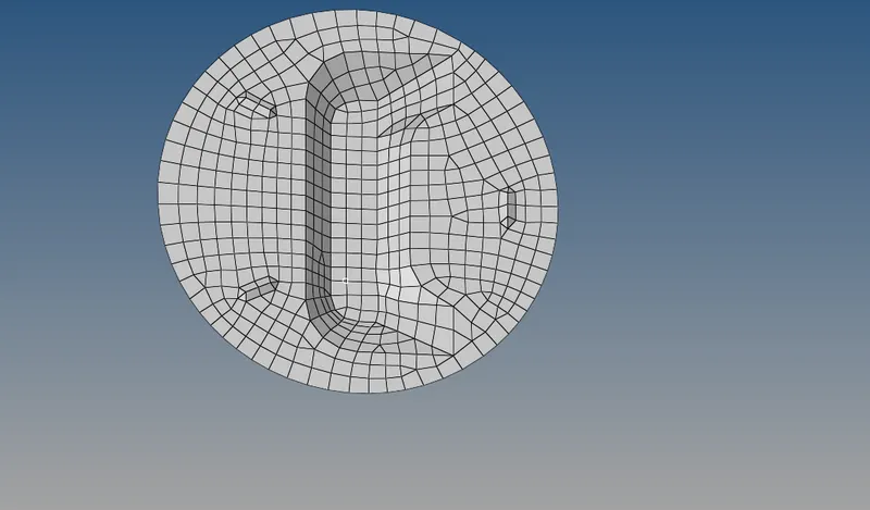
below image if mesh this region sheared edge very muscvh near thus that if mashing in this region elemnt falior occure so that first made onether line so that element not falior happend.
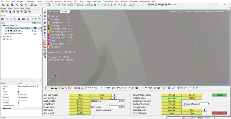
Line made and tolggle the line by using (Geom>Quick edit>line created by node to line tool > toggle line)
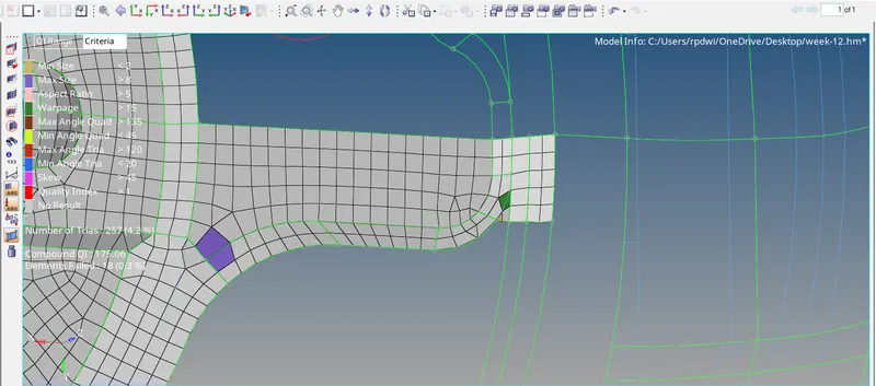
After meshing found some element faliour occure rebuild this surface by using (2D>Rebuild >select the surface >By Geom>Rebuild)
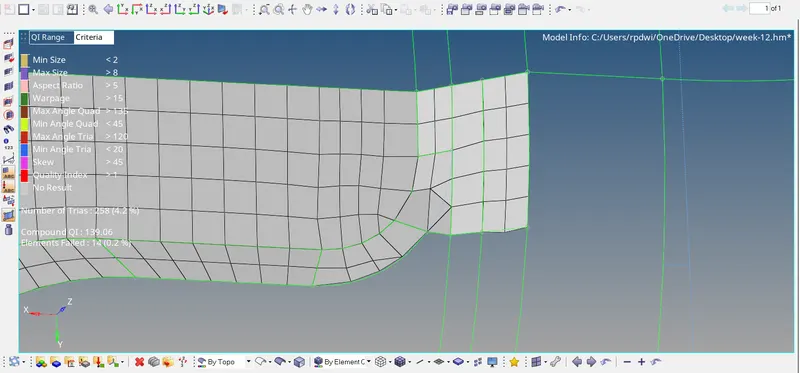
in this below image elemenate this max size error by using Decrease element size by select Node to node option
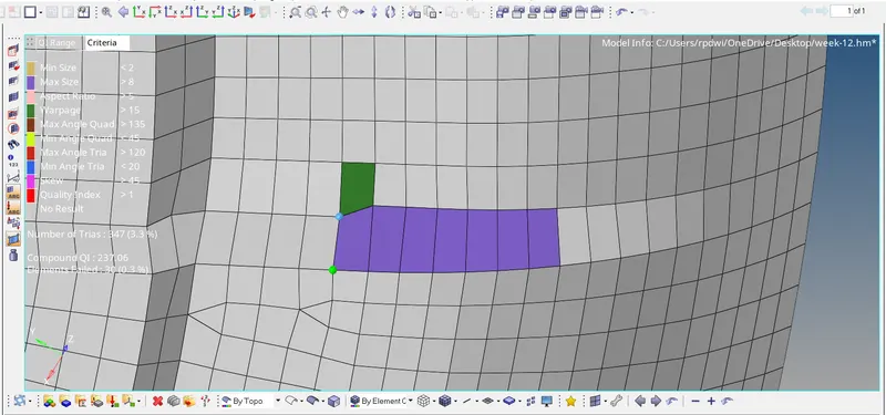
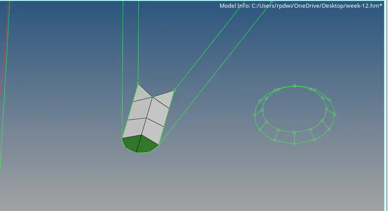
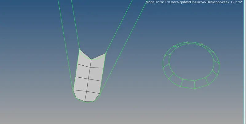
Heare opposite tiras hear to elemenate this split thise tria and connect eachother by using this tool (2D>Quality index>Split/Collapse edge)
once the tria connected each other than combine two tria by using combine tria element
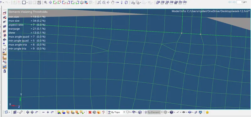
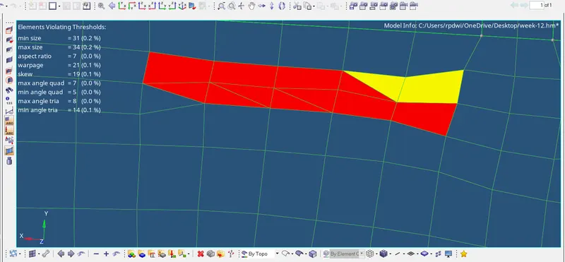
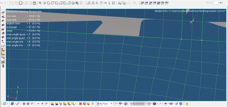
After doing all the operation found below result first now reduse trias % as much as can also zero element failed.
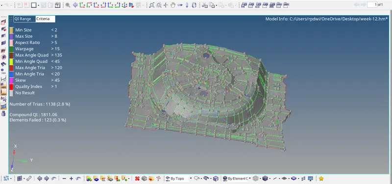
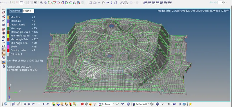
To do this follow given stage
● Use 2D>>Quality index tool >> Clean up tools (Smooth,drag tri elements, Element optimize, combine tria element Split quad element. Place node) to eliminate all off elements
● Smooth this option helps us to achieve better mesh flow. After clearing off elements, we usually use smooth in that area
● Drag Tria Element we can drag any Ma element out of the geometry easily The option helps us to remove trim easily
● Split Quad Element Splits one quad into two tom We use this to reduce rotating quads
● Combine Pm Elements Combines two Ma dements into one Quad element Miss In Reducing Ma percentage
● Element Optimize Smooths the quality by adjusting the neighboring deco,. Helps in Clearing elements for quality
● Place Node The option allows us to manually change the position of a single node Helps us to clear off elements
● We can use all the above options or if u want to remove quality issues automatically, use 2D >>Element clean-up option
● Have used all the clean up tools as these will give us better results than the etem ent clean-up opt on
● Mesh flow is good and all the trios are moving in same direction (no opposite trias)
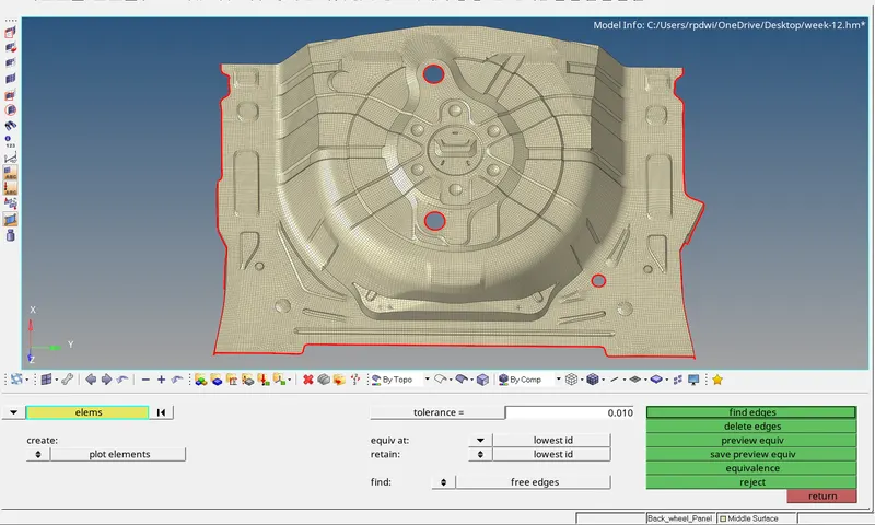
5) Check free Edge:-
By using tool (Tool>Edge>Select Element by displayed>Find)
As below image
If no error noticed, delete edges . Else, Select the elements where there are Free Edges within the geometry → preview equiv → equivalence → return.
Click on edges again and confirm that the free edges have been removed.
Also improve this by using Replace the node 2D>Replace/F3
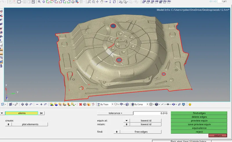
No free Edge present
6) Assigning Thickness:
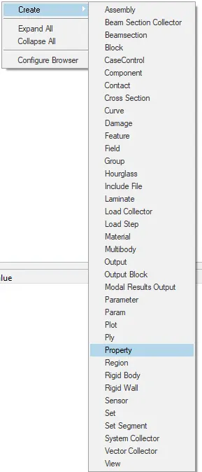
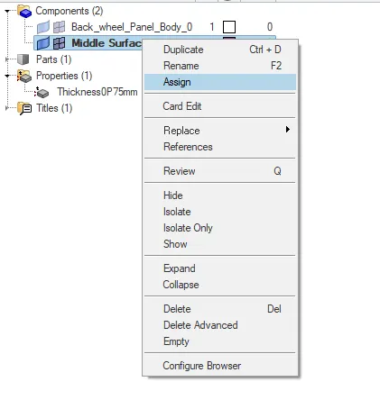
The next step is to assign the thickness. For doing this, a property should be created. A property can be created by right clicking on the tab bar, a pop-up appears Which indicates the "Create " Option.
7) LEARNING OUTCOMES:
At the end of this challenge, I can able to
- In this project,I came to know
- How to mesh a complex sheetmetal component.
- How to extract the mid surface manually for the complex sheetmetal components.
- How to clean complex geometry .
- How to generate a proper mesh flow with low tria percentage.
- How to assign thickness to the components.
8) CONCLUSTION:
- Hence, the geometrical errors and mesh, with the given element Quality criteria has been performed successfuly.
- As per methodology, From import cad, geometry clean up to mesh improvement phases have been performed successfuly.
- The Applying load & Boundry condition phases will be performed on upcoming phases.
9) Final image