Week 12:Project 2-Meshing of Rear Wheel Holder challenge
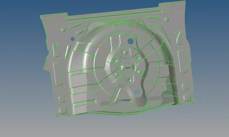
Objective: To mesh the given panel geometry by extracting the mid surface, along with that have to maintain a proper mesh flow and low tria concentration. The elements should pass the given quality criteria.
main CAD model:
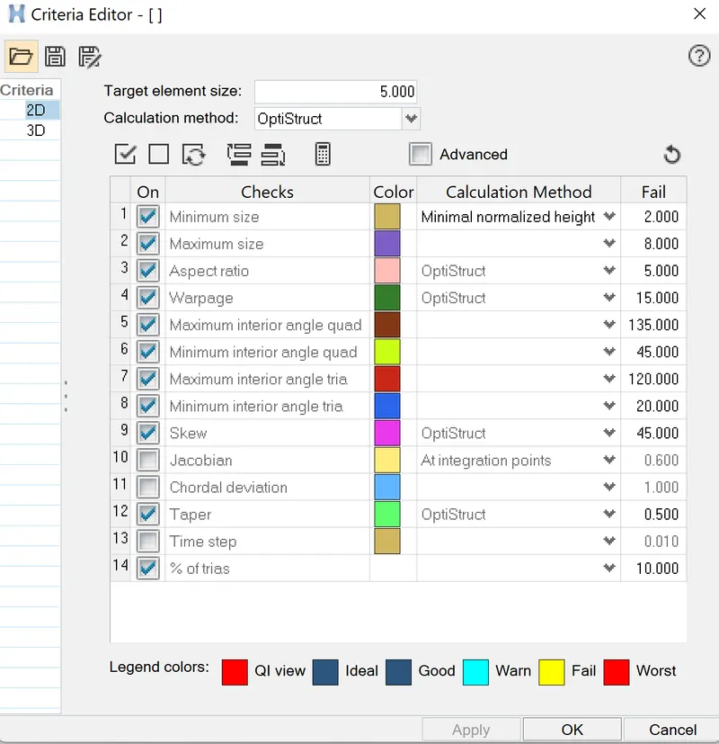
Quality criteria:
| S.N | Quality Criteria | Value |
| 1 | Aspect Ratio | 5 |
| 2 | Skewness | 45 |
| 3 | Warping | 15 |
| 4 | Taper | 0.5 |
| 5 | Min. Length | 2 Units |
| 6 | Max. Length | 8 Units |
| 7 | Min angle Quad | 45 |
| 8 | Max angle Quad | 135 |
| 9 | Min angle Tria | 20 |
| 10 | Max angle Tria | 120 |
| 10 | Tria % | 10 |
Procedure:
1. After importing the model first check whether the model is solid or a surface component, if it has solid we have to delete the solids from the delete option(F2).
2. organize the surfaces into one component because it has many tiny surfaces which are separated. Organizing can take place by using the tool option( Tools>organize).
select the surfaces which is to be move and select dest component and finally move.

3. The given panel geometry has a uniform thickness, therefore, the mid-surface extraction takes place manually and in some of the regions we can go with the offset option. The geometry has a thickness of 0.75mm and the offsets value is used 0.375mm.
surface edit > offset>select surface> check vector normal/ color normal> offset.

After selecting the surface duplicate it to the current component i,e mid surface component. because it creates another surface other than the parent surface.
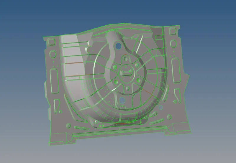
After extracting the mid surface in some of the area the connectivity is missed and became free edges in that area the stitches have been taking place.
a command like quick edit(F11)> toggle edge is used.
4. The small areas like billets has been deleted for the proper meshing process and to pass quality criteria.
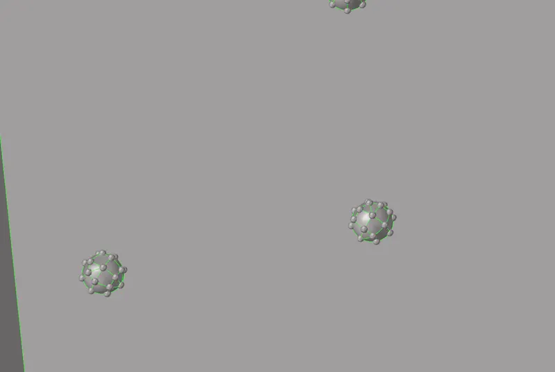
splitting of the surfaces is not much required but in some regions, it is required. unwanted lines are deleted and the model is prepared for the meshing process. By using the command quick edit(F11).
5. Before entering the meshing process we have to set the quality criteria files in the criteria files setting.
6. We should begin meshing from a certain place and move outward from there, as is common with meshing (preferably one with more free edges). In order to improve mesh control, we can utilize cut lines to separate the surface into smaller surfaces (quick edit > split surface node). The automesh tool can be accessed from the 2D set of options. 5 mm is the desired element length.
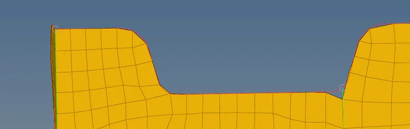
7. In the middle part of the floor panel, there are a few parts with narrow edges and the circle having the issue of warpages and the edges failing for minimum size trias, so such an issue is fixed by toggling the line at a certain distance and then joining them again. Those warpage are fixed by giving some trias at a distance or on the particular warpage element.
8. the opposite trias are merged together by using edit elements(F6). this command is also used for the splitting of the elements. the tria elements which are connected to each other were separated by using this option also.

9. In some of the areas like converging areas the trias will appear because of no uniform area is available. If we clear the tria elements in that regions will leads failure of other elements. Therefore trias are kept as it is.
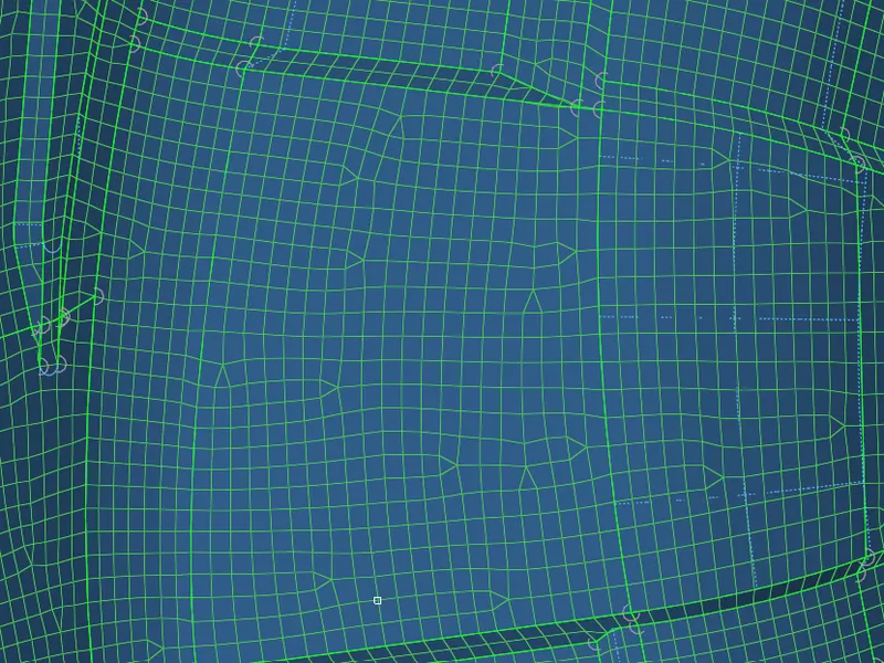
10. after the adjustment of the elements the smooth command is used for the elements to obtain a proper flow of mesh.There are many warpages in this component as a result of surface glitches and some small surfaces, which are fixed by new methods that check the element's degree before translating it by a value between 0.1 and 0.5. Some warpages are fixed by these methods by giving distance to the direction they follow, while others are fixed by splitting the quad into the tria.
11. we equivalence the entire meshed components to check whether the elements are aligned properly or not. It is misaligned the equivalence is checked between a range of 0.2 to 2 and has a tolerance value.
Tools>edges>elem> preview equivalence> equivalence.

12. After equivalence, we can use the check elements tool in the same menu to look for duplicates. If there are duplicates, we can choose "save failed," go to the tool menu, choose "delete," choose "elements," right-click "element," choose "retrieve," and finally choose "delete." The duplicates should be handled by this.
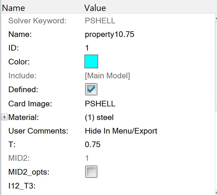
13. Finally, we may give each of our midsurfaces a thickness, which is 0.75 mm. Right-clicking and adding a component in the component tree will let us accomplish this. We can go to a property's section in the bottom left and scroll down to assign the aforementioned thickness after it has been created and given the name "Thickness."

Final model
result:
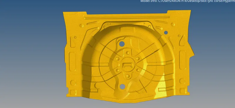
The panel geometry is meshed after extracting the midsurface. the mesh flow carried as per the best and the elements are suited the given quality criteria. In some of the region the elements are failed for the quality criteria because in that area the surface had avery tiny and curved surface features. In some regions the feature lines are toggled to maitain a good meshing. property and the matreials is also applied to to the model.